Hyundai Palisade (LX2): Fuel Delivery System / Components and components location
| Components Location |
| Fuel Tank & Filter-Neck Assembly |
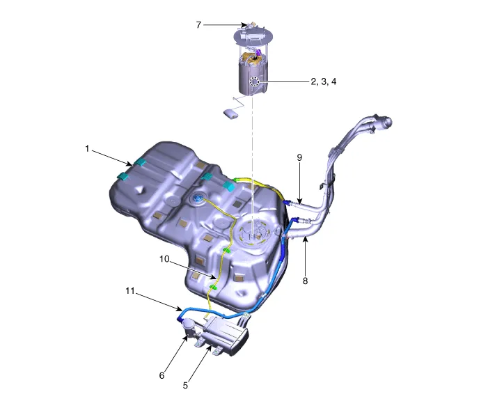
| 1. Fuel tank 2. Fuel pump 3. Fuel filter 4. Fuel pressure regulator 5. Canister 6. Fuel tank air filter |
7. Fuel Pressure sensor 8. Fuel Filler hose 9. Leveling hose 10. Ventilation hose 11. Vapor tube |
| High Pressure Fuel Line |
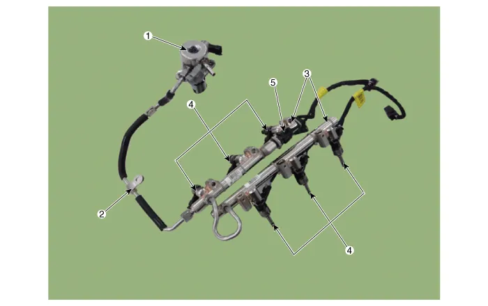
| 1. High Pressure Fuel Pump 2. High Pressure Fuel Pipe 3. Delivery Pipe |
4. Injector 5. Rail Pressure Sensor (RPS) |
|

Fuel Pressure Test (Low pressure system) 1. Release the residual pressure in fuel line. (Refer to Fuel Delivery System - "Release Residual Pressure in Fuel Line") ã When removing the fuel pump fuse, a Diagnostic Trouble Code (DTC) may occur.
Other information:
Hyundai Palisade (LX2) 2020-2026 Service Manual: Heater Unit
Components and components location Component Location 1. Heater unit assembly Components 1. Heater core assembly 2. Heater unit pad 3. Heater lower cover 4. Drain hose 5.
Hyundai Palisade (LX2) 2020-2026 Service Manual: Special service tools
Special Service Tools Tool Name / Number Illustration Description LKA Compensator (09890-3V100) Used for compensating front view camera unit Tolerance Compensation Plate for Surround View Monitoring (09957-CM100)
Categories
- Manuals Home
- Hyundai Palisade Owners Manual
- Hyundai Palisade Service Manual
- Electrochromatic Mirror (ECM) with homelink system
- Convenient Features of Your Vehicle
- Rear Heater Unit
- New on site
- Most important about car
