Hyundai Palisade (LX2): Coupling Assembly / Direct Electro Hydraulic Actuator Coupling
Components and components location
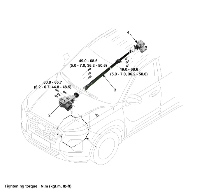
1. Trasaxle
assembly
2. Transfer assembly
|
3. Propeller
shaft assembly
4. Coupling assembly
|
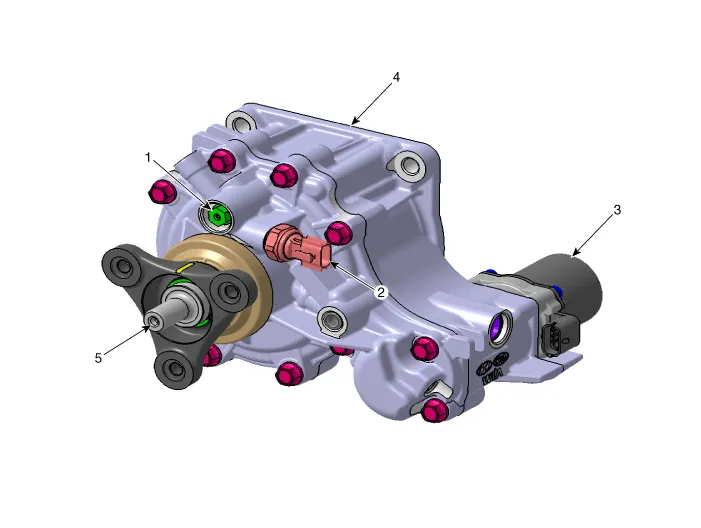
1. Relief
valve
2. Pressure sensor
3. Oil hydraulic motor
|
4. Coupling
asesmbly
5. Input shaft
|
Description and operation
AWD ECU processes signals from various sensors and determines the current road
and driving conditions. The ECU then utilizes this information to implement
precision control over the AWD coupling's multi-plate clutch and variably adjust
the amount of torque delivered tothe rear wheels.
AWD Driving mode
| – |
Under the conditions requiring high driving power such as start/hill
climbing/low speed, the front and rear power distribution rate is 5:5.
Under the driving conditions which do not require driving power such
as constant speed/deceleration, the vehicle operates automatically in
2WD (excluding SAND/MUD/SPORT)
|
| – |
On the slippery road such as snowy/icy road, smooth escape performance
is realized by automatically distributing the driving power.
|
| – |
Based on the selected Terrain Mode, control is focused on driving stability
and escape performance for SNOW and rough road driving performance is
secured in SAND/MUD through high driving power and driving power distribution
rate.
|
Electronic Coupling - AWD Control (By Driving Condition)
| 1. |
Driving conditions
| 1) |
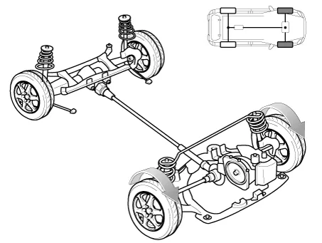
Cruising
- Power is delivered mostly to the front wheels.
Driving power distribution (front wheel 100%, rear wheel 0%)
|
| 2) |
Cornering
- Adjusts the amount of power to the rear wheels based on the
turning radius and cornering speed.
Driving power distribution (front wheel 80%, rear wheel 20%
or front wheel\ 50%, rear wheel 50%)

|
| 3) |
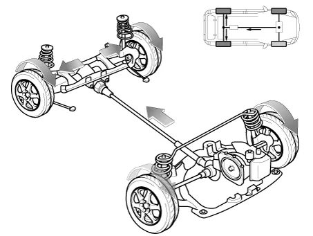
In case of start and rapid acceleration
- Steady driving power is delivered to the front and rear wheels
in case of start and rapid acceleration
Driving power distribution (front wheel 50%, rear wheel 50%
or front wheel 60%, rear wheel 40%)
|
|
| 2. |
Terrain mode
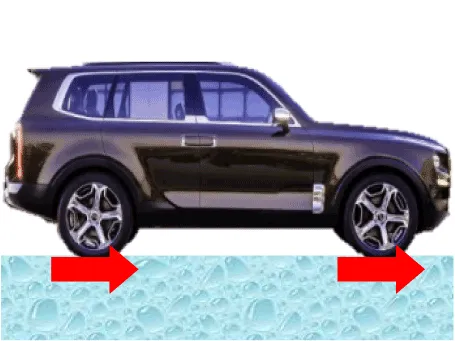
| 1) |
When driving on snowy road (slippery and even road surface)
- Safety-centered low power driving
Driving power distribution (front wheel 50%, rear wheel 50%)
|
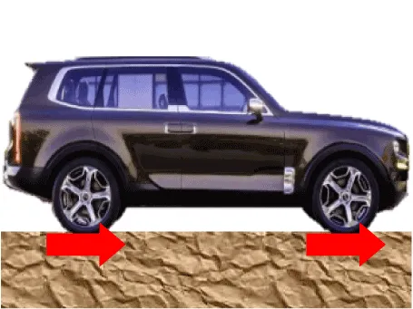
| 2) |
When driving on sandy road (road surface with high driving resistance)
- High power driving
Driving power distribution (front wheel 50%, rear wheel 50%)
|
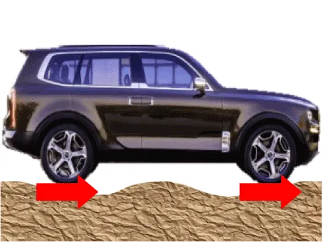
| 3) |
When driving on muddy road (slippery and uneven road surface)
- Escape performance and running stability
Driving power distribution (front wheel 50%, rear wheel 50%)
|
|
| 1. |
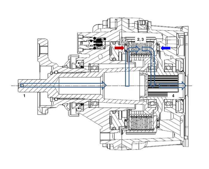
The power is delivered in the following order:
Transmission -> Transfer -> Propeller shaft
|
| 2. |
AWD ECU calculates the necessary amount of rear-wheel torque
and sends the corresponding driving current to the actuator
(electronic motor and hydraulic pump).
|
| 3. |
The piston operates by the oil pressure and the friction is
generated. Then, the clutch is engaged.
|
| 4. |
The power is delivered to the differential by the engaged clutch
and the driving power is generated in to the rear wheel.
|
|
Repair procedures
| • |
All units are filled up with coupling fluid (ultra-low viscosity
ATF) prior to shipping. Inspection, fill-up, and replacement
of coupling fluid is therefore not necessary (zero maintenance,
lifetime fluid).
|
|
|
Coupling Maintenance Precautions
Maintain the coupling at a horizontal level.
| • |
Refer to the handling caution level (A) when servicing the coupling
(removal, installation, replacement, etc.).
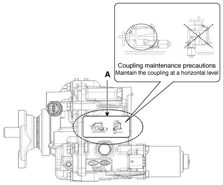
|
| • |
Always maintain a horizontal posture.
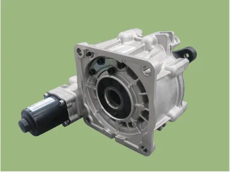
|
|
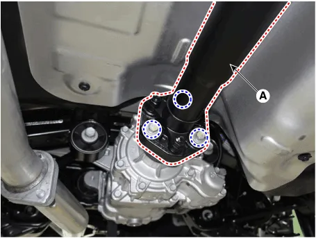
| 1. |
Loosen the rear propeller shaft assembly mounting bolts and then removing
the rear propeller shaft assembly (A).
|
Tightening torque :
49.0 - 68.6N.m (5.0 - 7.0kgf.m, 36.2 - 50.6lb-ft)
|
|
| 2. |
Using a flat tool, separate the propellar shaft from AWD coupling assembly.
|
| 3. |
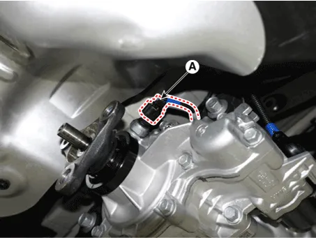
Disconnect the oil hydrulic motor connector (A).
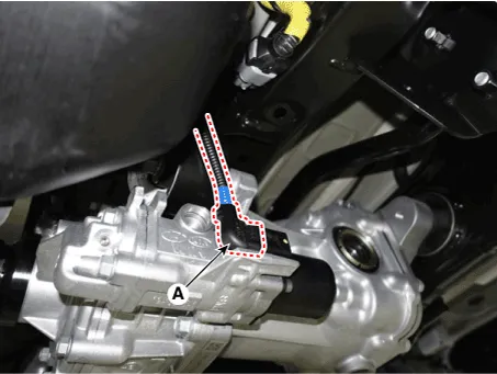
|
| 4. |
Disconnect the pressure sensor connector (A).
|
| 5. |
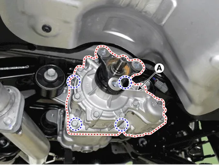
Loosen the coupling assembly mounting bolts.
|
Tightening torque :
58.9 - 64.7 N.m (5.8 - 6.6kgf.m, 41.9 - 47.7 lb-ft)
|
|
| 6. |
Using a flat tool, separate the AWD coupling assembly (A) from the rear
differential carrier assembly.
|
| 1. |
To install, reverse the removal procedures.
| •
|
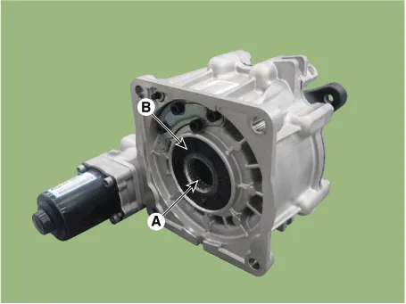
Smear the splines (A) with molybdenum type high pressure
grease.
|
| •
|
When install the coupling, be careful not to damage
the oil seal (B).
|
|
|
| 2. |
After replacing the coupling, reset the AWD ECU's clutch learing using
the diagnotic tool.
(Refer to AWD Control System - "Repair procedures")
|
Description and operation
Description
The AWD ECM controls the Pump Motor Pump (Actuator) to generating an oil pressure.
The pressure engages a multiple disk clutch to transfer torque to the rear wheels.
Other information:
Description and operation
Description
The auto defogging sensor is installed on the front window glass. The sensor
judges and sends signal if moisture occurs to blow out wind for defogging. The
air conditioner control module receives signal from the sensor and restrains
moisture and eliminate defog by controlling the intak
Special Service Tools
Tool Name / Number
Illustration
Description
LKA Compensator
(09890-3V100)
Used for compensating front view camera unit
Tolerance Compensation Plate for Surround View Monitoring
(09957-CM100)


