Hyundai Palisade: Heater / Evaporator Core
Hyundai Palisade (LX2) 2020-2025 Service Manual / Heating,Ventilation And Air Conditioning / Heater / Evaporator Core
Repair procedures
| Replacement |
| 1. |
Disconnect the negative (-) battery terminal.
|
| 2. |
Remove the heater and blower assembly.
(Refer to Heater - "Heater Unit")
|
| 3. |
Remove the heater core.
(Refer to Heater - "Heater Core")
|
| 4. |
Loosen the mounting screws and remove the evaporator core cover (A).
|
| 5. |
Separate the evaporator temperature sensor (A) from the evaporator core.
|
| 6. |
Remove the evaporator core (A) from the heater unit.
|
| 7. |
Install in the reverse order of removal.
|
 Heater Core
Repair procedures
Replacement
1.
Disconnect the negative (-) battery terminal.
2.
Remove the heater and blower assembly...
 PTC Heater (Diesel only)
Description and operation
Description
The PTC (Positive Temperature Coefficient) heater is installed at the exit or
the backside of the heater core...
Other information:
Hyundai Palisade (LX2) 2020-2025 Owner's Manual: Non-Powered Liftgate
Opening the liftgate Before attempting to open the liftgate, make sure the vehicle is in P (Park). To open the liftgate, perform one the following: 1. Unlock all doors with the Door Unlock button on your remote key or smart key. From outside press the liftgate handle switch and open the liftgate...
Hyundai Palisade (LX2) 2020-2025 Service Manual: Room Lamp
Repair procedures Removal Room lamp 1. Disconnect the negative (-) battery terminal. 2. Detach the lamp lens (A) from the room lamp with a flat-tip screwdriver. 3...
Categories
- Manuals Home
- 1st Generation Palisade Owners Manual
- 1st Generation Palisade Service Manual
- Automatic Door Lock and Unlock Features
- Changing Tires
- Normal Maintenance Schedule (3.8 GDI)
- New on site
- Most important about car
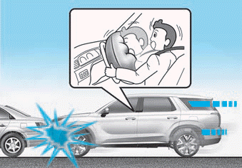
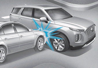
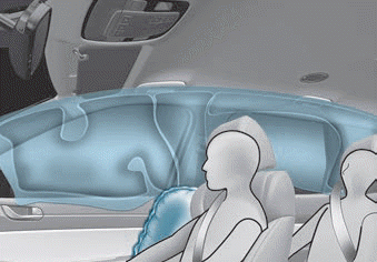
Air bag inflation conditions

Front air bags
Front air bags and the driver's knee air bag are designed to inflate in a frontal collision depending on the the severity of impact of the front collision.


Copyright © 2025 www.hpalisadelx.com


