Hyundai Palisade: Front Suspension System / Front Stabilizer Bar
Hyundai Palisade (LX2) 2020-2025 Service Manual / Suspension System / Front Suspension System / Front Stabilizer Bar
Repair procedures
| Removal |
| 1. |
Turn the ignition switch OFF and disconnect the battery negative (-)
cable.
|
| 2. |
Turn the steering wheel so that the front wheels are placed in the straight
ahead position.
|
| 3. |
Remove the front wheel and tire (A) from front hub.
|


| 4. |
Disconnect the stabilizer link with the front strut assembly after loosening
the nut (A).
|


| 5. |
Remove the tie rod end ball joint.
|


| 6. |
Remove the split pin and nut (A).
|

| 7. |
Remove the lower arm from the knuckle by using the SST (09568-4R100).
|

| 8. |
Loosen the bolt (A) and then disconnect the universal joint assembly
from the pinion of the steering gear box.
|


| 9. |
Remove the under cover.
(Refer to Engine Mechanical System - "Engine Room Under Cover")
|
| 10. |
Disconnect the R-MDPS main connector (A). [R-MDPS Type only]
|

| 11. |
Remove the muffler rubber hanger (A).
|

| 12. |
Remove the roll rod bracket (C) by loosening the bolt (A), (B).
|

| 13. |
Remove the subframe by loosening the mounting bolts and nuts.
|


| 14. |
Remove the heated protector (A).
[C-MDPS]
[R-MDPS]
|


| 15. |
Remove the steering gearbox (A) from the front sub frame by loosening
the mounting bolts.
[C-MDPS]
[R-MDPS]
|


| 16. |
Loosen the mounting bolts and then remove the stabilizer bar (A).
|

| Inspection |
| 1. |
Check the bushing for wear and deterioration.
|
| 2. |
Check the front stabilizer bar for deformation.
|
| 3. |
Check the front stabilizer link ball joint for damage.
|
| Installation |
| 1. |
Install in the reverse order of removal.
|
| 2. |
Check the alignment.
(Refer to Suspension System - "Alingment")
|
 Front Lower Arm
Repair procedures
Removal
1.
Loosen the wheel nuts slightly.
Raise the vehicle, and make sure it is securely supported...
 Sub Frame
Repair procedures
Removal
1.
Turn the ignition switch OFF and disconnect the battery negative (-)
cable.
2...
Other information:
Hyundai Palisade (LX2) 2020-2025 Service Manual: Engine Control Module (ECM)
Schematic diagrams ECM Terminal and Input / Output Signal ECM Terminal Function Connector [A] Pin No Description Connected to 1 Ignition Coil (Cylinder #4) control output Ignition Coil (Cylinder #4) 2 Injector (Cylinder #3) [High] control output Injector (Cylinder #3) 3 Injector (Cylinder #5) [High] control output Injector (Cylinder #5) 4 Injector (Cylinder #1) [High] control output Injector (Cylinder #1) 5 Camshaft Position Sensor (CMPS) [Bank 2 / Exhaust] signal input Camshaft Position Sensor (CMPS) [Bank 2 / Exhaust] 6 Camshaft Position Sensor (CMPS) [Bank 2 / Intake] signal input Camshaft Position Sensor (CMPS) [Bank 2 / Intake] 7 Throttle Position Sensor (TPS) 2 signal input Throttle Position Sensor (TPS) 2 8 - 9 Rail Pressure Sensor (RPS) signal input Rail Pressure Sensor (RPS) 10 CVVT Oil Temperature Sensor (OTS) signal input CVVT Oil Temperature Sensor (OTS) 11 - 12 - 13 Sensor power (+5V) CVVT Oil Temperature Sensor (OTS) Manifold Absolute Pressure Sensor (MAPS) 14 - 15 - 16 - 17 - 18 - 19 ETC Motor [-] control output ETC Motor 20 Heated Oxygen Sensor (HO2S) [Bank 1 / Sensor 1] Heater control output Heated Oxygen Sensor (HO2S) [Bank 1 / Sensor 1] 21 Heated Oxygen Sensor (HO2S) [Bank 2 / Sensor 1] Heater control output Heated Oxygen Sensor (HO2S) [Bank 2 / Sensor 1] 22 Ignition Coil (Cylinder #5) control output Ignition Coil (Cylinder #5 23 Injector (Cylinder #6) [High] control output Injector (Cylinder #6) 24 Injector (Cylinder #2) [High] control output Injector (Cylinder #2) 25 Injector (Cylinder #4) [High] control output Injector (Cylinder #4) 26 Camshaft Position Sensor (CMPS) [Bank 1 / Exhaust] signal input Camshaft Position Sensor (CMPS) [Bank 1 / Exhaust] 27 Camshaft Position Sensor (CMPS) [Bank 1 / Intake] signal input Camshaft Position Sensor (CMPS) [Bank 1 / Intake] 28 Intake Air Temperature Sensor (IATS) signal input Intake Air Temperature Sensor (IATS) 29 Manifold Absolute Pressure Sensor (MAPS) signal input Manifold Absolute Pressure Sensor (MAPS) 30 - 31 - 32 - 33 - 34 Sensor power (+5V) Camshaft Position Sensor (CMPS) [Bank 1 / Exhaust] Camshaft Position Sensor (CMPS) [Bank 2 / Intake] 35 - 36 Sensor power (+5V) Camshaft Position Sensor (CMPS) [Bank 1 / Intake] Camshaft Position Sensor (CMPS) [Bank 2 / Exhaust] 37 - 38 Purge Control Solenoid Valve (PCSV) control output Purge Control Solenoid Valve (PCSV) 39 - 40 ETC Motor [+] control output ETC Motor 41 - 42 - 43 Ignition Coil (Cylinder #1) control output Ignition Coil (Cylinder #1) 44 Injector (Cylinder #6) [Low] control output Injector (Cylinder #6) 45 Injector (Cylinder #3) [Low] control output Injector (Cylinder #3) 46 Injector (Cylinder #2) [Low] control output Injector (Cylinder #2) 47 Sensor ground Camshaft Position Sensor (CMPS) [Bank 1 / Exhaust] Camshaft Position Sensor (CMPS) [Bank 2 / Intake] 48 Sensor ground Manifold Absolute Pressure Sensor (MAPS) Oil Pressure Sensor (OPS) 49 Sensor ground Camshaft Position Sensor (CMPS) [Bank 1 / Intake] Camshaft Position Sensor (CMPS) [Bank 2 / Exhaust] 50 - 51 - 52 - 53 - 54 Engine Coolant Temperature Sensor (ECTS) signal input Engine Coolant Temperature Sensor (ECTS) 55 Sensor Shield Crankshaft Position Sensor (CKPS) Knock Sensor (KS) #1 [Bank 1] Knock Sensor (KS) #2 [Bank 2] 56 Sensor power (+5V) Rail Pressure Sensor (RPS) 57 - 58 Sensor ground Engine Coolant Temperature Sensor (ECTS) Rail Pressure Sensor (RPS) 59 Sensor ground Throttle Position Sensor (TPS) 1 Throttle Position Sensor (TPS) 2 60 Variable Intake Solenoid (VIS) Valve 1 control output Variable Intake Solenoid (VIS) Valve 1 61 Variable Intake Solenoid (VIS) Valve 2 control output Variable Intake Solenoid (VIS) Valve 2 62 - 63 - 64 Ignition Coil (Cylinder #2) control output Ignition Coil (Cylinder #2) 65 Injector (Cylinder #1) [Low] control output Injector (Cylinder #1) 66 Injector (Cylinder #4) [Low] control output Injector (Cylinder #4) 67 Injector (Cylinder #5) [Low] control output Injector (Cylinder #5) 68 Crankshaft Position Sensor (CKPS) [High] signal input Crankshaft Position Sensor (CKPS) 69 Crankshaft Position Sensor (CKPS) [Low] signal input Crankshaft Position Sensor (CKPS) 70 - 71 - 72 Oil pressure switch signal input Oil Pressure Sensor (OPS) 73 - 74 - 75 Throttle Position Sensor (TPS) 1 signal input Throttle Position Sensor (TPS) 1 76 Knock Sensor (KS) [Bank 1] [Low] signal input Knock Sensor (KS) [Bank 1] 77 Knock Sensor (KS) [Bank 2] [Low] signal input Knock Sensor (KS) [Bank 2] 78 Sensor ground Heated Oxygen Sensor (HO2S) [Bank 2 / Sensor 2] 79 Rc/Rp (Pump Cell Voltage) Heated Oxygen Sensor (HO2S) [Bank 2 / Sensor 1] 80 VS+ (NERNST Cell Voltage) Heated Oxygen Sensor (HO2S) [Bank 2 / Sensor 1] 81 Heated Oxygen Sensor (HO2S) [Bank 2 / Sensor 2] signal input Heated Oxygen Sensor (HO2S) [Bank 2 / Sensor 2] 82 VS+ (NERNST Cell Voltage) Heated Oxygen Sensor (HO2S) [Bank 1 / Sensor 1] 83 Rc (Compensative Resistance) Heated Oxygen Sensor (HO2S) [Bank 1 / Sensor 1] 84 Oil Pressure Solenoid Valve control output Oil Pressure Solenoid Valve 85 Ignition Coil (Cylinder #6) control output Ignition Coil (Cylinder #6) 86 Ignition Coil (Cylinder #3) control output Ignition Coil (Cylinder #3) 87 Fuel Pressure Control Valve (FPCV) [High] control output Fuel Pressure Control Valve (FPCV) 88 Fuel Pressure Control Valve (FPCV) [Low] control output Fuel Pressure Control Valve (FPCV) 89 Heated Oxygen Sensor (HO2S) [Bank 2 / Sensor 2] Heater control output Heated Oxygen Sensor (HO2S) [Bank 2 / Sensor 2] 90 Heated Oxygen Sensor (HO2S) [Bank 1 / Sensor 2] Heater control output Heated Oxygen Sensor (HO2S) [Bank 1 / Sensor 2] 91 CVVT Oil Control Valve (OCV) [Bank 2 / Exhaust] control output CVVT Oil Control Valve (OCV) [Bank 2 / Exhaust] 92 CVVT Oil Control Valve (OCV) [Bank 1 / Exhaust] control output CVVT Oil Control Valve (OCV) [Bank 1 / Exhaust] 93 Variable Force Solenoid (VFS) [Bank 2 / Intake] control output Variable Force Solenoid (VFS) [Bank 2 / Intake] 94 Variable Force Solenoid (VFS) [Bank 1 / Intake] control output Variable Force Solenoid (VFS) [Bank 1 / Intake] 95 - 96 Sensor power (+5V) Throttle Position Sensor (TPS) 1 Throttle Position Sensor (TPS) 2 97 Knock Sensor (KS) [Bank 1] [High] signal input Knock Sensor (KS) [Bank 1] 98 Knock Sensor (KS) [Bank 2] [High] signal input Knock Sensor (KS) [Bank 2] 99 Sensor ground Heated Oxygen Sensor (HO2S) [Bank 1 / Sensor 2] 100 - 101 Rc (Compensative Resistance) Heated Oxygen Sensor (HO2S) [Bank 2 / Sensor 1] 102 VS-/IP- (Common ground) Heated Oxygen Sensor (HO2S) [Bank 2 / Sensor 1] 103 Heated Oxygen Sensor (HO2S) [Bank 1 / Sensor 2] signal input Heated Oxygen Sensor (HO2S) [Bank 1 / Sensor 2] 104 VS-/IP- (Common ground) Heated Oxygen Sensor (HO2S) [Bank 1 / Sensor 1] 105 Rc/Rp (Pump Cell Voltage) Heated Oxygen Sensor (HO2S) [Bank 1 / Sensor 1] Connector [K] Pin No Description Connected to 1 ECM ground Chassis ground 2 ECM ground Chassis ground 3 Battery power (B+) Main Relay 4 ECM ground Chassis ground 5 Battery power (B+) Main Relay 6 Battery power (B+) Main Relay 7 - 8 - 9 - 10 - 11 - 12 - 13 Sensor ground A/C Pressure Transducer (APT) 14 Immobilizer communication line Immobilizer Control Module 15 Fuel Level Sender (FLS) signal input [Fuel pump] Fuel Level Sender (FLS) 16 - 17 - 18 - 19 - 20 Sensor power (+5V) Accelerator Position Sensor (APS) 1 21 Main Relay control output Main Relay 22 - 23 - 24 - 25 - 26 - 27 - 28 Accelerator Position Sensor (APS) 2 signal input Accelerator Position Sensor (APS) 2 29 - 30 - 31 - 32 Fuel Level Sender (FLS) signal input [Sub Fuel Sender] Sub Fuel Level Sender 33 Fuel Pump Relay control output Fuel Pump Relay 34 - 35 Sensor power (+5V) A/C Pressure Transducer (APT) 36 Sensor power (+5V) Accelerator Position Sensor (APS) 2 37 - 38 Vehicle speed signal input VDC control module 39 - 40 - 41 Start signal input Start Relay 42 - 43 - 44 - 45 - 46 - 47 Sensor ground Accelerator Position Sensor (APS) 2 48 - 49 Brake Switch [Test] signal input Brake Switch 50 - 51 - 52 Sensor ground Accelerator Position Sensor (APS) 1 53 - 54 - 55 - 56 - 57 - 58 - 59 - 60 P-CAN [Low] Other control module, Data Link Connector (DLC), Multi-Purpose Check Connector 61 - 62 - 63 - 64 A/C Pressure Transducer (APT) signal input A/C Pressure Transducer (APT) 65 - 66 - 67 - 68 - 69 LIN (Local Interconnect Network) Serial Bus Line Battery Sensor 70 - 71 Cooling Fan Relay control output Cooling Fan Relay 72 Engine speed signal output Integrated Body Control Unit (IBU) 73 - 74 - 75 - 76 - 77 P-CAN [High] Other control module, Data Link Connector (DLC), Multi-Purpose Check Connector 78 - 79 Start Relay control output Start Relay 80 - 81 - 82 Accelerator Position Sensor (APS) 1 signal input Accelerator Position Sensor (APS) 1 83 Brake Switch [Light] signal input Brake Switch 84 - 85 - 86 - 87 - 88 - 89 - 90 - 91 - ECM Terminal Input/ Output signal Connector [A] Pin No Description Condition Type Level 1 Ignition Coil (Cylinder #4) control output Idle Pulse Vpeak = 400V Frequency : 0 - 58...
Hyundai Palisade (LX2) 2020-2025 Owner's Manual: Sunshade
■ Front ■ Rear Front To open the sunshade, pull the sunroof sunshade backward. To close the sunshade, pull the sunroof sunshade forward. Rear (if equipped) To open the rear blind, push the rear blind OPEN button. To close the rear blind, push the rear blind CLOSE button...
Categories
- Manuals Home
- 1st Generation Palisade Owners Manual
- 1st Generation Palisade Service Manual
- Fuse/Relay Panel Description
- Emergency liftgate safety release
- Automatic Door Lock and Unlock Features
- New on site
- Most important about car
How Does the Air Bag System Operate?
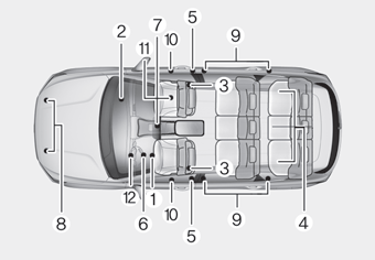
The SRS consists of the following components:
1. Driver's front air bag module
2. Passenger's front air bag module
3. Side air bag modules
4. Curtain air bag modules
5. Retractor pre-tensioner
6. Air bag warning light
7. SRS control module (SRSCM)/
Rollover sensor
8. Front impact sensors
9. Side impact sensors
10.Side pressure sensors
11. Occupant classification system
12. Driver’s knee airbag module

Copyright © 2025 www.hpalisadelx.com