Hyundai Palisade (LX2): Fuses And Relays / ICM (Integrated Circuit Module) Relay Box
Hyundai Palisade (LX2) 2020-2026 Service Manual / Body Electrical System / Fuses And Relays / ICM (Integrated Circuit Module) Relay Box
Description and operation
| Description |
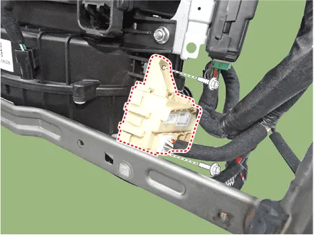
The ICM relay is united with (rear wiper relay, seat heater relay(front/rear),
head lamp washer relay and rear A/C relay) which installed inside the lower
crash pad.
Repair procedures
| Inspection |
Power Child Lock
Check for continuity between the terminals.
| 1. |
There should be continuity between the No.15 and No.7 terminals when
power and ground are connected to the No.15 and No.14 in the ICM-A.
|
| 2. |
There should be continuity between the No.10 and No.12 terminals when
power and ground are connected to the No.15 and No.14 in the ICM-A.
|
Power Child Unlock
Check for continuity between the terminals.
| 1. |
There should be continuity between the No.11 and No.12 terminals when
power and ground are connected to the No.11 and No.1 in the ICM-A.
|
| 2. |
There should be continuity between the No.10 and No.7 terminals when
power and ground are connected to the No.11 and No.1 in the ICM-A.
|
Description and operation Dscription and Operation ICU (Integrated Central Control Unit) ICU (Integrated Central Control Unit) is an integrated model of smart junction block and central gateway.
Categories
- Manuals Home
- Hyundai Palisade Owners Manual
- Hyundai Palisade Service Manual
- How to reset the power liftgate
- Rear Heater Unit
- Repair procedures
- New on site
- Most important about car

Copyright © 2026 www.hpalisadelx.com - 0.0116