Hyundai Palisade (LX2): Power Door Mirrors / Power Door Mirror Switch
Schematic diagrams
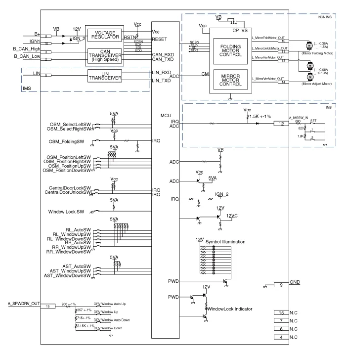
| Circuit Diagram |
Repair procedures
| Removal |
| 1. |
Disconnect the negative (-) battery terminal.
|
| 2. |
Remove the front left door trim.
(Refer to Body - "Front Door Trim")
|
| 3. |
Disengage the mounting clip and then remove the door rock switch assembly
(A).
|

| Installation |
| 1. |
Install the power mirror switch.
|
| 2. |
Install the front door trim after connecting the connector.
|
| 3. |
Connect the negative (-) battery terminal.
|
| Inspection |
| 1. |
In the body electrical system, failure can be quickly diagnosed by using
the vehicle diagnostic system (Diagnostic tool).
The diagnostic system (Diagnostic tool) provides the following information.
|
| 2. |
If diagnose the vehicle by Diagnostic tool, select "DTC Analysis" and
"Vehicle".
|

| 3. |
If check current status, select the "Data Analysis" and "Car model".
|

| 4. |
Select the 'IBU_BCM' to search the current state of the input/output
data.
|


| 5. |
To forcibly actuate the input value of the module to be checked, select
option 'Actuation Test'.
|

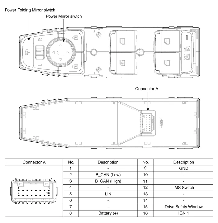
Component Location 1. Power door mirror 2. Power door mirror switch 3. Power folding mirror switch
Repair procedures Removal 1. Disconnect (-) battery terminal. 2. Using a fastener remover (C), remove the mirror (A) as illustration below.
Other information:
Hyundai Palisade (LX2) 2020-2026 Service Manual: Description and operation
Description and Operation Blcok Diagram • This system monitors the driving situations through the radar and the camera. Thus, for a situation out of the sensing range, the system may not normally operate.
Hyundai Palisade (LX2) 2020-2026 Service Manual: Schematic diagrams
Trouble Symptom Charts Component Parts and Function Outline Component part Function Cruise Control Switch Input the set speed and distance to the SCC ECU. Instrument Cluster Display various information inputted from SCC.
Categories
- Manuals Home
- Hyundai Palisade Owners Manual
- Hyundai Palisade Service Manual
- Lift and Support Points
- Engine Mechanical System
- Resetting the Driver's Seat Memory System
- New on site
- Most important about car
