Hyundai Palisade: Multifunction Switch / Repair procedures
Hyundai Palisade (LX2) 2020-2025 Service Manual / Body Electrical System / Multifunction Switch / Repair procedures
| Removal |
| 1. |
Disconnect the negative (-) battery terminal.
|
| 2. |
Remove the steering wheel.
(Refer to Steering System - "Steering Wheel")
|
| 3. |
Remove the steering column upper and lower shrouds.
(Refer to Body - "Steering Column Shroud Panel")
|
| 4. |
Remove the clock spring.
(Refer to Retraint - "Driver Airbag (DAB) Module and Clock Spring)
|
| 5. |
Disconnect the multifunction switch connector (A).
|

| 6. |
Loosen the screws (2EA) and then remove the multifunction switch assembly
(A).
|

| Installation |
| 1. |
Install the multifunction switch.
|
| 2. |
Install the clock spring and steering wheel.
|
| 3. |
Install the steering column upper and lower shrouds.
|
| 4. |
Install the steering wheel.
|
| Inspection |
Multifunction Switch Inspection
| 1. |
Check for continuity between the terminals in each switch position as
shown below.
|

Inspection (With Diagnostic tool)
| 1. |
In the body electrical system, failure can be quickly diagnosed by using
the vehicle diagnostic system (Diagnostic tool).
The diagnostic system (Diagnostic tool) provides the following information.
|
| 2. |
If diagnose the vehicle by Diagnostic tool, select "DTC Analysis" and
"Vehicle".
|

| 3. |
If check current status, select the "Data Analysis" and "Car model".
|

| 4. |
Select the 'IBU_BCM' to search the current state of the input/output
data.
|


 Horn
Horn
..
Other information:
Hyundai Palisade (LX2) 2020-2025 Service Manual: Description and operation
..
Hyundai Palisade (LX2) 2020-2025 Owner's Manual: To decrease the Smart Cruise Control set speed
Follow either of these procedures: Push the toggle switch down (SET-), and release it immediately. The cruising speed will decrease by 1 mph (1 km/h) each time you move the toggle switch down in this manner. Push the toggle switch down (SET-), and hold it...
Categories
- Manuals Home
- 1st Generation Palisade Owners Manual
- 1st Generation Palisade Service Manual
- Check Tire Pressure
- Electronic Child Safety Lock System
- Normal Maintenance Schedule (3.8 GDI)
- New on site
- Most important about car
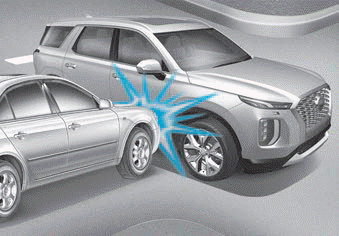
Air bag inflation conditions
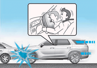
Front air bags
Front air bags and the driver's knee air bag are designed to inflate in a frontal collision depending on the the severity of impact of the front collision.

Copyright © 2025 www.hpalisadelx.com