Hyundai Palisade (LX2): Crash Pad / Steering Column Shroud Panel
Components and components location
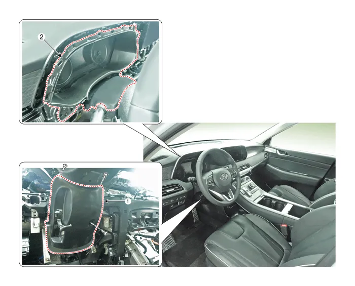
1. Steering column shroud lower
panel
|
2. Steering column shroud upper
panel
|
Repair procedures
[Steering column shroud upper panel]
| • |
When removing with a flat-tip screwdriver or remover, wrap protective
tape around the tools to prevent damage to components.
|
| • |
Put on gloves to prevent hand injuries.
|
|
| • |
Use a plastic panel removal tool to remove interior trim pieces
without marring the surface.
|
| • |
Take care not to bend or scratch the trim and panels.
|
|
| 1. |
Remove the front center fascia panel.
(Refer to Crash Pad - "Center fascia panel")
|
| 2. |
Remove the crash pad lower panel.
(Refer to Crash Pad - "Crash pad lower panel")
|
| 3. |
Loosen the mounting screws and remove the side air vent duct [LH] (A).

|
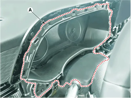
| 4. |
Loosen the mounting screws and remove the steering column shroud upper
panel (A).
|
| 5. |
To install, reverse removal procedure.
| •
|
Replace any damaged clips (or pin-type retainers).
|
|
|
[Steering column shroud lower panel]
| • |
When removing with a flat-tip screwdriver or remover, wrap protective
tape around the tools to prevent damage to components.
|
| • |
Put on gloves to prevent hand injuries.
|
|
| • |
Use a plastic panel removal tool to remove interior trim pieces
without marring the surface.
|
| • |
Take care not to bend or scratch the trim and panels.
|
|
| 1. |
Remove the crash pad lower panel.
(Refer to Crash Pad - "Crash pad lower panel")
|
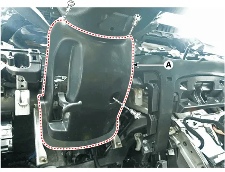
| 2. |
Loosen the mounting screws by turning the steering wheel to the left
and right, and remove the steering column shroud lower panel (A).
|
| 3. |
To install, reverse removal procedure.
| •
|
Replace any damaged clips (or pin-type retainers).
|
|
|
Components and components location
Component Location
1. Crash pad lower panel
Repair procedures
Replacement
•
When removing with a flat-tip screwdriver or remover, wrap protective
tape around the tools to prevent damage to components.
Components and components location
Component Location
[LH]
1. Crash pad side cover [LH]
[RH]
1.
Other information:
Description and operation
Description
The PTC (Positive Temperature Coefficient) heater is installed at the exit or
the backside of the heater core.
The PTC heater is an electric heater using a PTC element as an auxiliary heating
device that supplements deficiency of interior heat source in highly effective
diesel engi
Description
The smart cruise control system allows a driver to program the vehicle to control
the speed and following distance by detecting the vehicle ahead without depressing
the brake pedal or the accelerator pedal.
1.


