
Hyundai Palisade (LX2): ESP(Electronic Stability Program) System / Yaw-rate and G Sensor
Description and operation
| Description |
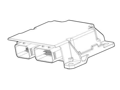
Repair procedures
| Removal |
| 1. |
Turn ignition switch OFF and disconnect the negative (-) battery cable.
|

| 2. |
Remove the floor console.
(Refer to Body - "Floor Console")
|
| 3. |
Pull up the lock, of the SRSCM connector, the disconnect the connector.
|

| 4. |
Remove the SRSCM mounting bolts (3EA) from the SRSCM, then remove the
SRSCM.
|


| Installation |
| 1. |
To install, reverse the removal procedures.
|
| 2. |
Perform Longitudinal G-sensor calibration in vehicle S/W Management
menu of the GDS.
|
| Adjustment |
| 1. |
Connect self-diagnosis connector(16pins) located in the lower of driver
side crash pad to self-diagnosis device, and then turn the self-diagnosis
device after key is ON.
|
| 2. |
Select the "vehicle model" and "ABS/ESP" on GDS vehicle selection screen,
then select OK.
[Longitudinal G Sensor Calibration]
|

Description and operation Description Introduction of quick brake warning system (ESS) In case of quick brake by driver, the brake lamp or turn signal is blinked to warn against the vehicle at rear.
Description and operation Description The DBC function is the acronym word of Downhill Brake Control function. When a vehicle goes down the hill, just pushing the DBC switch enables the car to keep its vehicle's speed at a constant value without operating the brake pedal.
Other information:
Hyundai Palisade (LX2) 2020-2026 Service Manual: Photo Sensor
Description and operation Description The photo sensor is located at the center of the defrost nozzles. The photo sensor contains a photovoltaic (sensitive to sunlight) diode. The solar radiation received by its light receiving portion, generates an electromotive force in proportion to the amount of radiation received wh
Hyundai Palisade (LX2) 2020-2026 Service Manual: Schematic diagrams
System Block Diagram Component Parts And Function Outline Component part Function Vehicle-speed sensor, ESP/ABS Control Module Converts vehicle speed to pulse. ECM Receives signals from sensor and control switches.
Categories
- Manuals Home
- Hyundai Palisade Owners Manual
- Hyundai Palisade Service Manual
- Troubleshooting
- Rain Sensor
- Electrochromatic Mirror (ECM) with homelink system
- New on site
- Most important about car
