Hyundai Palisade: Parking Distance Warning (PDW) / Description and operation
Hyundai Palisade (LX2) 2020-2025 Service Manual / Advanced Driver Assistance System (ADAS) / Parking Distance Warning (PDW) / Description and operation
| Description |
| • |
PDW consists of 8 sensors (front : 4 units, rear : 4 units) that are
used to detect obstacles and transmit the result in three separate warning
levels, the first, second and third to IBU via LIN communication.
|
| • |
IBU decides the alarm level by the transmitted communication message
from the slave sensors, then operates the buzzer or transmits the data
for display.
|
Block Diagram

System Operation Specification
| Initial mode |
| 1. |
System initializing time
|
| 2. |
PDW recognizes LID and sets the sensor ID up during initialization.
|
| 3. |
PDW activates each sensor and then executes the diagnosis after finishing
initialization of IPM(IBU).
|
| 4. |
PDW starting buzzer is normally worked, when sensor does not send an
error message and after finishing error diagnosis.
|
| 5. |
If any failure is received from the any sensors, PDW starting buzzer
does not work but the failure alarm is operated for a moment.
If you have display option, warning sign is also shown on it.
|

| 6. |
IBU memorizes the completed initializing status of sensor.
|
| Normal mode |
| 7. |
PDW-F : Lin communication starts and keeps the routine after IGN1 ON+D
gear + below 10 km/h.
PDW-R : Lin communication starts and keeps the routine after IGN1 ON+R
gear
|
| 8. |
After initializing, the routine starts at once without PDW starting
warning sound.
|
| 9. |
Alarms of obstacle consists of 3 level 1,2,3 step and 1,2 alarm sounds
intermittently and 3 alarm sounds continuously. 1 level alarm doesn't
exist in the front ultrasonic sensor.
|
| 10. |
In display, the data of each sensor is sent from IBU to display, for
example cluster. CAN communication is used for transmission and maximum
gateway time is 50ms.
|
| 11. |
The efficient vehicle speed of PDW operation is under 10Km/h.
|
| 12. |
Operation doesn't start or stops at gear N, P.
|
Sensing Area
|
Level |
Distance range |
Allowed range |
|
1 |
Front : 61 - 100 cm (24.02 - 39.37 in.) / Rear : 61 - 120 cm (24.02 - 47.2
in.) |
± 15 cm (5.90 in.) |
|
2 |
31 - 60 cm (12.20 - 23.62 in.) |
± 15 cm (5.90 in.) |
|
3 |
0 - 30 cm (0 - 11.81 in) |
± 10 cm (3.94 in.) |
*Measurement condition : PVC pipe - Diameter 75 mm (0.0394 in.), length 1 m
(39.37 in.), at normal temperature
Display Alarm Indicator Specification

 Components and components location
Component Location
1. IBU (Integrated Body Control
Unit)
2. Parking distance warning sensor
※ Parking Distance Warning function is built in IBU (Integrated Body Control
Unit)...
 Ultrasonic Sensor
Schematic diagrams
Schematic Diagrams
Repair procedures
Removal
1.
Remove the bumper cover.
(Refer to Body - "Front Bumper Cover")
(Refer to Body - "Rear Bumper Cover")
2...
Other information:
Hyundai Palisade (LX2) 2020-2025 Service Manual: Oil Temperature Sensor (Main Harness)
Specifications Specification ▷ Type: Negative Thermal Coefficient Type Temp [(°C)°F] Resistance (kΩ) (-40) -40 48.1 (-20) -4.0 15.6 (0) 32...
Hyundai Palisade (LX2) 2020-2025 Owner's Manual: Side View Mirrors
Make sure to adjust the side view mirrors to your desired position before you begin driving. Your vehicle is equipped with both left-hand and right-hand side view mirrors. The mirrors can be adjusted remotely with the remote switch. The side view mirrors can be folded to help prevent damage when going through an automatic car wash or when passing through a narrow street...
Categories
- Manuals Home
- 1st Generation Palisade Owners Manual
- 1st Generation Palisade Service Manual
- Auto Hold
- AC Inverter
- Normal Maintenance Schedule (3.8 GDI)
- New on site
- Most important about car
How Does the Air Bag System Operate?
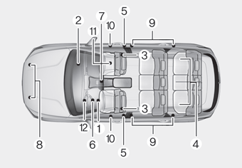
The SRS consists of the following components:
1. Driver's front air bag module
2. Passenger's front air bag module
3. Side air bag modules
4. Curtain air bag modules
5. Retractor pre-tensioner
6. Air bag warning light
7. SRS control module (SRSCM)/
Rollover sensor
8. Front impact sensors
9. Side impact sensors
10.Side pressure sensors
11. Occupant classification system
12. Driver’s knee airbag module

Copyright © 2025 www.hpalisadelx.com