Hyundai Palisade: Fuel Delivery System / Fuel Line
Repair procedures
| Removal |
|
|
High pressure fuel pipe [High Pressure Fuel Pump ↔ Delivery pipe]
| 1. |
Release the residual pressure in fuel line.
(Refer to Fuel Delivery System - "Release Residual Pressure in Fuel
Line")
|
| 2. |
Switch "OFF" the ignition and disconnect the negative (-) battery terminal.
|
| 3. |
Remove the control wiring harness (A).
|
| 4. |
Remove the high pressure fuel pipe mounting bolts (A).
|
| 5. |
Remove the high pressure fuel pipe flange nut (B).
|
| 6. |
Remove the high pressure fuel pipe (A).
|
High Pressure Fuel Line [Delivery Pipe (Bank 1) Line ↔ Delivery Pipe (Bank 2)
Line]
| 1. |
Release the residual pressure in fuel line.
(Refer to Fuel Delivery System - "Release Residual Pressure in Fuel
Line")
|
| 2. |
Switch "OFF" the ignition and disconnect the negative (-) battery terminal.
|
| 3. |
Remove the air cleaner assembly.
(Refer to Engine Mechanical System - "Air Cleaner")
|
| 4. |
Remove the surge tank.
(Refer to Engine Mechanical System - "Surge Tank")
|
| 5. |
Remove the intake manifold
(Refer to Engine Mechanical System - "Intake Manifold")
|
| 6. |
Remove the cross over high pressure fuel pipe (A).
|
Low Pressure Fuel Line [High Pressure Fuel Pump ↔ Extension Fuel Line]
| 1. |
Release the residual pressure in fuel line.
(Refer to Fuel Delivery System - "Release Residual Pressure in Fuel
Line")
|
| 2. |
Switch "OFF" the ignition and disconnect the negative (-) battery terminal.
|
| 3. |
Remove the control wiring harness (A).
|
| 4. |
Remove the fuel line mounting bolts (A).
|
| 5. |
Remove the low pressure fuel line mounting nuts (B).
|
| 6. |
Remove the low pressure fuel line (A).
|
Low Pressure Fuel Line [Fuel Tank <-> Extension Fuel Line]
| 1. |
Release the residual pressure in fuel line.
(Refer to Fuel Delivery System - "Release Residual Pressure in Fuel
Line")
|
| 2. |
Turn ignition switch OFF and disconnect the negative (-) battery terminal.
|
| 3. |
Remove the air cleaner assembly.
(Refer to Engine Mechanical System - "Air Cleaner")
|
| 4. |
Remove the low fuel line (A) after loosening the mounting nuts.
|
| 5. |
Disconnect the vapor hose (B).
|
| 6. |
Remove the fuel line fixing clip (A).
|
| 7. |
Lift the vehicle.
|
| 8. |
Remove the fuel line fixing clip (A).
|
| 9. |
Remove the fuel tank.
(Refer to Fuel Delivery System - "Fuel Tank")
|
| 10. |
Open the vapor tube and fuel feed line fixing clip (A) to using driver.
|
| Installation |
| 1. |
Install in the reverse order of removal.
|
| Inspection |
| 1. |
Visually check the fuel lines for cracks, leakage, loose connections,
deformation or tank band looseness.
|
 Fuel Pressure Regulator
Repair procedures
Removal
1.
Remove the fuel pump.
(Refer to Fuel Delivery System - "Fuel Pump")
2...
 Filler-Neck Assembly
Repair procedures
Removal
1.
Turn the ignition switch OFF and disconnect the battery negative (-)
cable.
2...
Other information:
Hyundai Palisade (LX2) 2020-2025 Service Manual: Description and operation
Description Burglar Alarm State [B/A State] B/A State Description DISARM 1) In "DISARM" state, no vehicle start inhibition. So, when door, hood, or Tailgate is opened, there is no alarm sound and flashing...
Hyundai Palisade (LX2) 2020-2025 Owner's Manual: Low Tire Pressure Telltale
Low Tire Pressure LCD Display with Position Indicator When the tire pressure monitoring system warning indicators are illuminated and the warning message is displayed on the cluster LCD display, one or more of your tires is significantly under-inflated...
Categories
- Manuals Home
- 1st Generation Palisade Owners Manual
- 1st Generation Palisade Service Manual
- Emergency liftgate safety release
- Electrochromatic Mirror (ECM) with homelink system
- How to reset the power liftgate
- New on site
- Most important about car
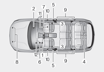
How Does the Air Bag System Operate?

The SRS consists of the following components:
1. Driver's front air bag module
2. Passenger's front air bag module
3. Side air bag modules
4. Curtain air bag modules
5. Retractor pre-tensioner
6. Air bag warning light
7. SRS control module (SRSCM)/
Rollover sensor
8. Front impact sensors
9. Side impact sensors
10.Side pressure sensors
11. Occupant classification system
12. Driver’s knee airbag module
Copyright © 2025 www.hpalisadelx.com


