Hyundai Palisade: Lighting System / Head Lamps

Hyundai Palisade (LX2) 2020-2025 Service Manual / Body Electrical System / Lighting System / Head Lamps

Repair procedures
Removal
Hyundai Palisade. Repair procedures   
Head lamps become very hot during use; do not touch them or any attaching hardware immediately after they have been turned off.
Hyundai Palisade. Repair procedures   
The headlamp bulb should not be removed from the headlamp assembly until just before a new bulb is installed.
Removing bulb for an extended period of time may affect headlamp bulb performance.
Contaminants may enter the headlamp assembly where they can settle on the lens and reflector.
Never turn on the head lamps with the bulb removed from the headlamp assembly.
1.
Disconnect the negative (-) battery terminal.
2.
Remove the front bumper cover.
(Refer to Body - "Front Bumper Cover")
3.
Disconnecting the lamp connectors (A).

Hyundai Palisade. Repair procedures

4.
Loosen the mounting bolts and then remove the head lamp assembly (A).

Hyundai Palisade. Repair procedures

Hyundai Palisade. Repair procedures   
Take care that retaining clip (A) is not to be damaged.
5.
Remove the dust caps (A) from the headlamp assembly after turning in the counterclockwise direction.

Hyundai Palisade. Repair procedures

6.
Disconnect the connector and then remove the bulb.
Installation
1.
Install the head lamp bulb.
2.
Install the dust cover.
3.
Install the head lamp assembly after connecting the lamp connector.
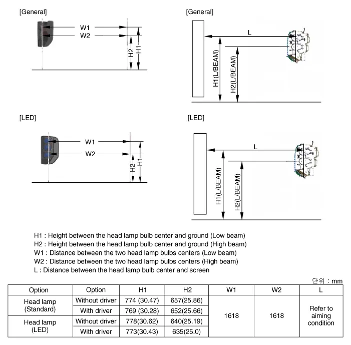
Head Lamp Aiming Instructions
1.
Alternately turn the adjusting gear to adjust the head lamp aiming. If beam-setting equipment is not available, proceed as follows :
2.
The vehicle should be placed on a flat ground.s
3.
Draw vertical lines (Vertical lines passing through respective head lamp centers) and a horizontal line (Horizontal line passing through center of head lamps) on the screen.
4.
With the head lamp and battery in normal condition, aim the head lamps so the brightest portion falls on the horizontal and vertical lines.
A : Vertical (High beam / Low beam)

Hyundai Palisade. Repair procedures

Head Lamp And Fog Lamp Aiming Point

Hyundai Palisade. Repair procedures

1.
Head Lamp (Low beam)
With the low beam turned on, adjust the cut-off line to be located as shown in the picture below.
If head lamp leveling device is equipped, adjust the head lamp leveling device switch with 0 positions.

Hyundai Palisade. Repair procedures

2.
Head Lamp (High Beam)
Turn the high beam on without driver aboard.
The cut-off line should be projected in the cut-off line shown in the picture.
When aiming the low beam, vertical aiming shuld be adjusted after adjusting the horizontal aiming.
If head lamp leveling device is equipped, adjust the head lamp leveling device switch with 0 positions.

Hyundai Palisade. Repair procedures

3.
With the front fog lamp turned on, adjust the cut-off line to be located as shown in the picture below.

Hyundai Palisade. Repair procedures

Head lamp fogging
Check the below instruction procedure when the head lamp is fogged.

Hyundai Palisade. Repair procedures

    Components and components location

    Component Location 1. Head lamp (Low) 2. Head lamp (High) 3. Head lamp (Spread Low) 4. Head lamp (Hot spot Low) 5...

    Turn Signal Lamp

    Repair procedures Removal Door mirror turn signal lamp    • Put on gloves to prevent hand injuries...

    Other information:

    Hyundai Palisade (LX2) 2020-2025 Service Manual: AVN Head Unit


    Components and components location Components Connector Pin Information No Connector A (ExternalAmplifier) Connector A (Internal Amplifier) Connector B Connector C 1 - Rear door speaker LH (+) - - 2 - Rear door speaker LH (-) Mic (+) I_CAN (High) 3 Navigation voice (+) - - - 4 External amplifier SPDIF (+) - - - 5 Reset Reset Antenna dummy power - 6 RVM : Camera Power , SVM : - RVM : Camera Power , SVM : - Illumination (+) - 7 RVM : Camera Video , SVM : - RVM : Camera Video , SVM : - M-CAN (High) - 8 - - - - 9 - - - - 10 - - Battery (+) - 11 AUX DETECT AUX DETECT Battery (+) - 12 Steering wheel remote Steering wheel remote Ground - 13 - Front door speaker LH (+) Ground - 14 - Front door speaker LH (-) - - 15 - Front door speaker RH (-) Mic (-) - 16 - Front door speaker RH (+) - (SVM type:SVM Detect2) MTS Key 17 Navigation voice (-) - - - 18 External amplifier SPDIF (-) - - - 19 External amplifier SPDIF (Ground) - Illumination (-) - 20 RVM : Camera Power GND , SVM : - RVM : Camera Power GND , SVM : - M-CAN (Low) - 21 RVM : Camera Video GND , SVM : - RVM : Camera Video GND , SVM : - - - 22 - - ACC 23 - - Keyboard Power 24 - - - 25 - - - 26 Steering wheel remote ground Steering wheel remote ground - 27 - Rear door speaker RH (-) - 28 - Rear door speaker RH (+) - 29 - - - 30 - - - 31 - - - 32 SVM DETECT 1 SVM DETECT 1 - 33 RVM : Camera Shield GND , SVM : - RVM : Camera Shield GND , SVM : - IGN 1 34 - - Keyboard GND 35 - - - 36 - - 37 - - 38 Vehicle speed Vehicle speed Repair procedures Removal 1...

    Hyundai Palisade (LX2) 2020-2025 Service Manual: Engine Control Module (ECM)


    Schematic diagrams ECM Terminal and Input / Output Signal ECM Terminal Function Connector [A] Pin No Description Connected to 1 Ignition Coil (Cylinder #4) control output Ignition Coil (Cylinder #4) 2 Injector (Cylinder #3) [High] control output Injector (Cylinder #3) 3 Injector (Cylinder #5) [High] control output Injector (Cylinder #5) 4 Injector (Cylinder #1) [High] control output Injector (Cylinder #1) 5 Camshaft Position Sensor (CMPS) [Bank 2 / Exhaust] signal input Camshaft Position Sensor (CMPS) [Bank 2 / Exhaust] 6 Camshaft Position Sensor (CMPS) [Bank 2 / Intake] signal input Camshaft Position Sensor (CMPS) [Bank 2 / Intake] 7 Throttle Position Sensor (TPS) 2 signal input Throttle Position Sensor (TPS) 2 8 -   9 Rail Pressure Sensor (RPS) signal input Rail Pressure Sensor (RPS) 10 CVVT Oil Temperature Sensor (OTS) signal input CVVT Oil Temperature Sensor (OTS) 11 -   12 -   13 Sensor power (+5V) CVVT Oil Temperature Sensor (OTS) Manifold Absolute Pressure Sensor (MAPS) 14 -   15 -   16 -   17 -   18 -   19 ETC Motor [-] control output ETC Motor 20 Heated Oxygen Sensor (HO2S) [Bank 1 / Sensor 1] Heater control output Heated Oxygen Sensor (HO2S) [Bank 1 / Sensor 1] 21 Heated Oxygen Sensor (HO2S) [Bank 2 / Sensor 1] Heater control output Heated Oxygen Sensor (HO2S) [Bank 2 / Sensor 1] 22 Ignition Coil (Cylinder #5) control output Ignition Coil (Cylinder #5 23 Injector (Cylinder #6) [High] control output Injector (Cylinder #6) 24 Injector (Cylinder #2) [High] control output Injector (Cylinder #2) 25 Injector (Cylinder #4) [High] control output Injector (Cylinder #4) 26 Camshaft Position Sensor (CMPS) [Bank 1 / Exhaust] signal input Camshaft Position Sensor (CMPS) [Bank 1 / Exhaust] 27 Camshaft Position Sensor (CMPS) [Bank 1 / Intake] signal input Camshaft Position Sensor (CMPS) [Bank 1 / Intake] 28 Intake Air Temperature Sensor (IATS) signal input Intake Air Temperature Sensor (IATS) 29 Manifold Absolute Pressure Sensor (MAPS) signal input Manifold Absolute Pressure Sensor (MAPS) 30 -   31 -   32 -   33 -   34 Sensor power (+5V) Camshaft Position Sensor (CMPS) [Bank 1 / Exhaust] Camshaft Position Sensor (CMPS) [Bank 2 / Intake] 35 -   36 Sensor power (+5V) Camshaft Position Sensor (CMPS) [Bank 1 / Intake] Camshaft Position Sensor (CMPS) [Bank 2 / Exhaust] 37 -   38 Purge Control Solenoid Valve (PCSV) control output Purge Control Solenoid Valve (PCSV) 39 -   40 ETC Motor [+] control output ETC Motor 41 -   42 -   43 Ignition Coil (Cylinder #1) control output Ignition Coil (Cylinder #1) 44 Injector (Cylinder #6) [Low] control output Injector (Cylinder #6) 45 Injector (Cylinder #3) [Low] control output Injector (Cylinder #3) 46 Injector (Cylinder #2) [Low] control output Injector (Cylinder #2) 47 Sensor ground Camshaft Position Sensor (CMPS) [Bank 1 / Exhaust] Camshaft Position Sensor (CMPS) [Bank 2 / Intake] 48 Sensor ground Manifold Absolute Pressure Sensor (MAPS) Oil Pressure Sensor (OPS) 49 Sensor ground Camshaft Position Sensor (CMPS) [Bank 1 / Intake] Camshaft Position Sensor (CMPS) [Bank 2 / Exhaust] 50 -   51 -   52 -   53 -   54 Engine Coolant Temperature Sensor (ECTS) signal input Engine Coolant Temperature Sensor (ECTS) 55 Sensor Shield Crankshaft Position Sensor (CKPS) Knock Sensor (KS) #1 [Bank 1] Knock Sensor (KS) #2 [Bank 2] 56 Sensor power (+5V) Rail Pressure Sensor (RPS) 57 -   58 Sensor ground Engine Coolant Temperature Sensor (ECTS) Rail Pressure Sensor (RPS) 59 Sensor ground Throttle Position Sensor (TPS) 1 Throttle Position Sensor (TPS) 2 60 Variable Intake Solenoid (VIS) Valve 1 control output Variable Intake Solenoid (VIS) Valve 1 61 Variable Intake Solenoid (VIS) Valve 2 control output Variable Intake Solenoid (VIS) Valve 2 62 -   63 -   64 Ignition Coil (Cylinder #2) control output Ignition Coil (Cylinder #2) 65 Injector (Cylinder #1) [Low] control output Injector (Cylinder #1) 66 Injector (Cylinder #4) [Low] control output Injector (Cylinder #4) 67 Injector (Cylinder #5) [Low] control output Injector (Cylinder #5) 68 Crankshaft Position Sensor (CKPS) [High] signal input Crankshaft Position Sensor (CKPS) 69 Crankshaft Position Sensor (CKPS) [Low] signal input Crankshaft Position Sensor (CKPS) 70 -   71 -   72 Oil pressure switch signal input Oil Pressure Sensor (OPS) 73 -   74 -   75 Throttle Position Sensor (TPS) 1 signal input Throttle Position Sensor (TPS) 1 76 Knock Sensor (KS) [Bank 1] [Low] signal input Knock Sensor (KS) [Bank 1] 77 Knock Sensor (KS) [Bank 2] [Low] signal input Knock Sensor (KS) [Bank 2] 78 Sensor ground Heated Oxygen Sensor (HO2S) [Bank 2 / Sensor 2] 79 Rc/Rp (Pump Cell Voltage) Heated Oxygen Sensor (HO2S) [Bank 2 / Sensor 1] 80 VS+ (NERNST Cell Voltage) Heated Oxygen Sensor (HO2S) [Bank 2 / Sensor 1] 81 Heated Oxygen Sensor (HO2S) [Bank 2 / Sensor 2] signal input Heated Oxygen Sensor (HO2S) [Bank 2 / Sensor 2] 82 VS+ (NERNST Cell Voltage) Heated Oxygen Sensor (HO2S) [Bank 1 / Sensor 1] 83 Rc (Compensative Resistance) Heated Oxygen Sensor (HO2S) [Bank 1 / Sensor 1] 84 Oil Pressure Solenoid Valve control output Oil Pressure Solenoid Valve 85 Ignition Coil (Cylinder #6) control output Ignition Coil (Cylinder #6) 86 Ignition Coil (Cylinder #3) control output Ignition Coil (Cylinder #3) 87 Fuel Pressure Control Valve (FPCV) [High] control output Fuel Pressure Control Valve (FPCV) 88 Fuel Pressure Control Valve (FPCV) [Low] control output Fuel Pressure Control Valve (FPCV) 89 Heated Oxygen Sensor (HO2S) [Bank 2 / Sensor 2] Heater control output Heated Oxygen Sensor (HO2S) [Bank 2 / Sensor 2] 90 Heated Oxygen Sensor (HO2S) [Bank 1 / Sensor 2] Heater control output Heated Oxygen Sensor (HO2S) [Bank 1 / Sensor 2] 91 CVVT Oil Control Valve (OCV) [Bank 2 / Exhaust] control output CVVT Oil Control Valve (OCV) [Bank 2 / Exhaust] 92 CVVT Oil Control Valve (OCV) [Bank 1 / Exhaust] control output CVVT Oil Control Valve (OCV) [Bank 1 / Exhaust] 93 Variable Force Solenoid (VFS) [Bank 2 / Intake] control output Variable Force Solenoid (VFS) [Bank 2 / Intake] 94 Variable Force Solenoid (VFS) [Bank 1 / Intake] control output Variable Force Solenoid (VFS) [Bank 1 / Intake] 95 -   96 Sensor power (+5V) Throttle Position Sensor (TPS) 1 Throttle Position Sensor (TPS) 2 97 Knock Sensor (KS) [Bank 1] [High] signal input Knock Sensor (KS) [Bank 1] 98 Knock Sensor (KS) [Bank 2] [High] signal input Knock Sensor (KS) [Bank 2] 99 Sensor ground Heated Oxygen Sensor (HO2S) [Bank 1 / Sensor 2] 100 -   101 Rc (Compensative Resistance) Heated Oxygen Sensor (HO2S) [Bank 2 / Sensor 1] 102 VS-/IP- (Common ground) Heated Oxygen Sensor (HO2S) [Bank 2 / Sensor 1] 103 Heated Oxygen Sensor (HO2S) [Bank 1 / Sensor 2] signal input Heated Oxygen Sensor (HO2S) [Bank 1 / Sensor 2] 104 VS-/IP- (Common ground) Heated Oxygen Sensor (HO2S) [Bank 1 / Sensor 1] 105 Rc/Rp (Pump Cell Voltage) Heated Oxygen Sensor (HO2S) [Bank 1 / Sensor 1] Connector [K] Pin No Description Connected to 1 ECM ground Chassis ground 2 ECM ground Chassis ground 3 Battery power (B+) Main Relay 4 ECM ground Chassis ground 5 Battery power (B+) Main Relay 6 Battery power (B+) Main Relay 7 -   8 -   9 -   10 -   11 -   12 -   13 Sensor ground A/C Pressure Transducer (APT) 14 Immobilizer communication line Immobilizer Control Module 15 Fuel Level Sender (FLS) signal input [Fuel pump] Fuel Level Sender (FLS) 16 -   17 -   18 -   19 -   20 Sensor power (+5V) Accelerator Position Sensor (APS) 1 21 Main Relay control output Main Relay 22 -   23 -   24 -   25 -   26 -   27 -   28 Accelerator Position Sensor (APS) 2 signal input Accelerator Position Sensor (APS) 2 29 -   30 -   31 -   32 Fuel Level Sender (FLS) signal input [Sub Fuel Sender] Sub Fuel Level Sender 33 Fuel Pump Relay control output Fuel Pump Relay 34 -   35 Sensor power (+5V) A/C Pressure Transducer (APT) 36 Sensor power (+5V) Accelerator Position Sensor (APS) 2 37 -   38 Vehicle speed signal input VDC control module 39 -   40 -   41 Start signal input Start Relay 42 -   43 -   44 -   45 -   46 -   47 Sensor ground Accelerator Position Sensor (APS) 2 48 -   49 Brake Switch [Test] signal input Brake Switch 50 -   51 -   52 Sensor ground Accelerator Position Sensor (APS) 1 53 -   54 -   55 -   56 -   57 -   58 -   59 -   60 P-CAN [Low] Other control module, Data Link Connector (DLC), Multi-Purpose Check Connector 61 -   62 -   63 -   64 A/C Pressure Transducer (APT) signal input A/C Pressure Transducer (APT) 65 -   66 -   67 -   68 -   69 LIN (Local Interconnect Network) Serial Bus Line Battery Sensor 70 -   71 Cooling Fan Relay control output Cooling Fan Relay 72 Engine speed signal output Integrated Body Control Unit (IBU) 73 -   74 -   75 -   76 -   77 P-CAN [High] Other control module, Data Link Connector (DLC), Multi-Purpose Check Connector 78 -   79 Start Relay control output Start Relay 80 -   81 -   82 Accelerator Position Sensor (APS) 1 signal input Accelerator Position Sensor (APS) 1 83 Brake Switch [Light] signal input Brake Switch 84 -   85 -   86 -   87 -   88 -   89 -   90 -   91 -   ECM Terminal Input/ Output signal Connector [A] Pin No  Description Condition Type Level 1 Ignition Coil (Cylinder #4) control output Idle Pulse Vpeak = 400V Frequency : 0 - 58...

    Categories

    Seat Belt Warning Light

    Seat belt warning light

    Hyundai Palisade. Seat Belt Warning Light

    Driver's seat belt warning

    As a reminder to the driver, the seat belt warning light will illuminate for approximately 6 seconds each time you place the ignition switch to the ON position regardless of belt fastening. At this time, if the seat belt is not fastened a warning chime will sound for 6 seconds.

    read more


    Copyright © 2025 www.hpalisadelx.com