Hyundai Palisade (LX2): Power Windows / Power Window Switch
Components and components location
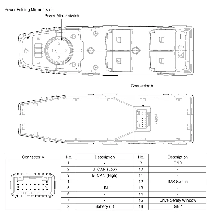
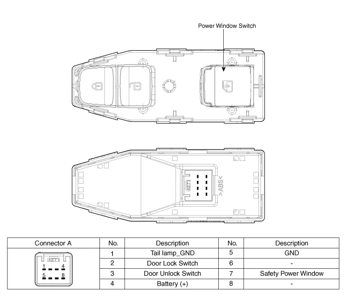
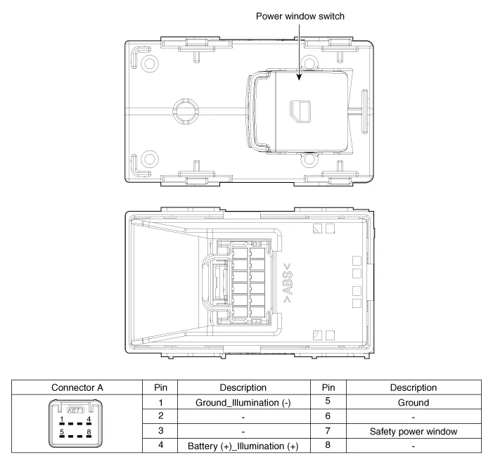
| Components |
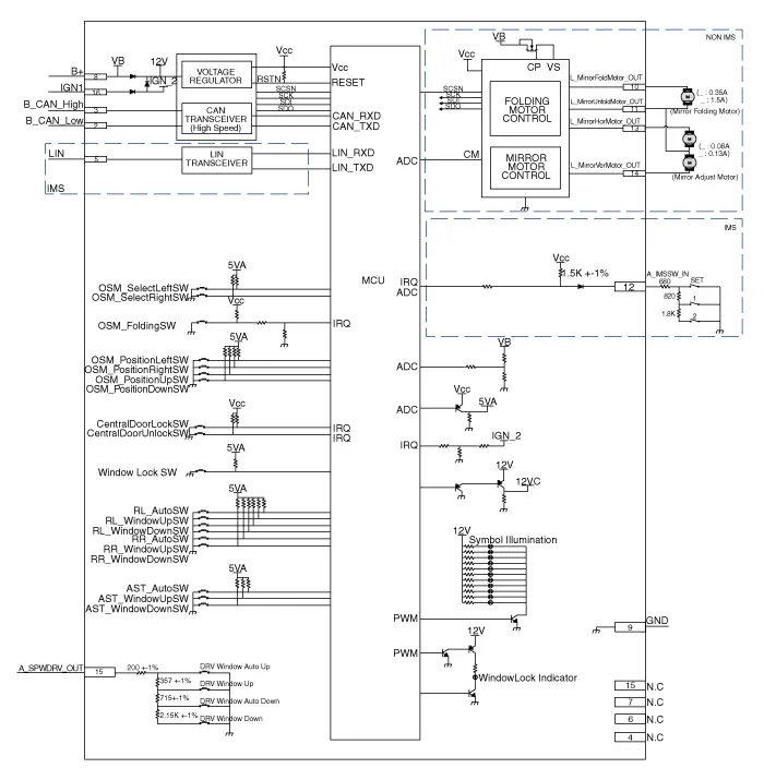
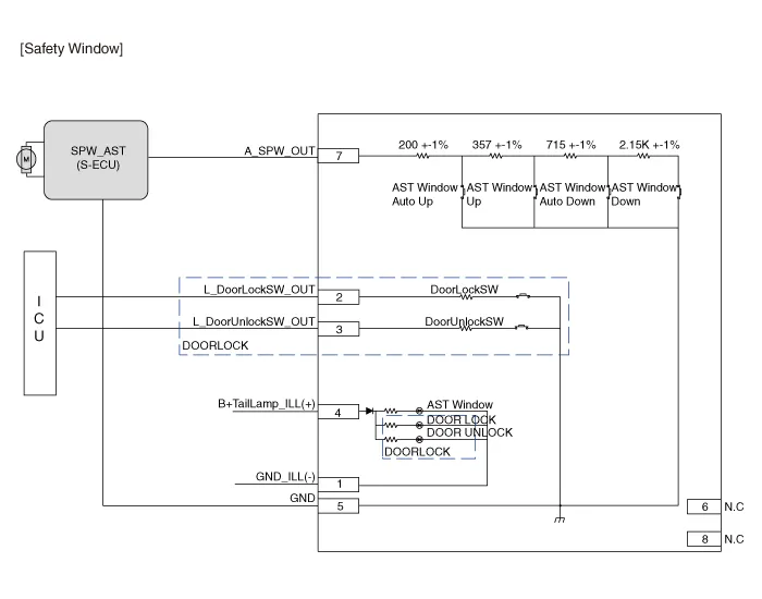
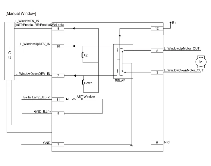
Schematic diagrams
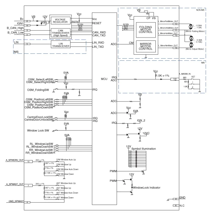
| Circuit Diagram |


Repair procedures
| Diagnosis with Diagnostic tool |
| 1. |
In the body electrical system, failure can be quickly diagnosed by using
the vehicle diagnostic system (Diagnostic tool).
The diagnostic system (Diagnostic tool) provides the following information.
|
| 2. |
If diagnose the vehicle by Diagnostic tool, select "DTC Analysis" and
"Vehicle".
|

| 3. |
Select the 'Data Analysis' and 'Car model'.
|

| 4. |
Select the 'DDM' to search the current state of the input/output data.
|


| 5. |
To forcibly actuate the input value of the module to be checked, select
option 'Actuation Test'.
|

| Removal |
| 1. |
Disconnect the negative (-) battery terminal.
|
| 2. |
Remove the front door trim.
(Refer to Body - "Front Door Trim")
|
| 3. |
Disengage the mounting clip and then remove the power window switch
assembly (A).
|

| 1. |
Disconnect the negative (-) battery terminal.
|
| 2. |
Remove the front door trim.
(Refer to Body - "Front Door Trim")
|
| 3. |
Disengage the mounting clip and then remove the power window switch
assembly (A).
|

| 1. |
Disconnect the negative (-) battery terminal.
|
| 2. |
Remove the rear door trim.
(Refer to Body - "Rear Door Trim")
|
| 3. |
Disengage the mounting clip and then remove the power window switch
assembly (A).
|

| Installation |
| 1. |
Install the power window switch assembly.
|
| 2. |
Install the front door trim after connecting the connector.
|
| 1. |
Install the power window switch assembly.
|
| 2. |
Install the front door trim after connecting the connector.
|
| 1. |
Install the power window switch assembly.
|
| 2. |
Install the rear door trim after connecting the connector.
|
Components and components location Components Repair procedures Inspection Front Power Window Motor 1. Disconnect the negative (-) battery terminal.
Other information:
Hyundai Palisade (LX2) 2020-2026 Service Manual: Mode Control Actuator
Description and operation Description The mode control actuator is located at the heater unit. It adjusts the position of the mode door by operating the mode control actuator based on the signal of the A/C control unit. Pressing the mode select switch makes the mode control actuator shift in order of Vent → Bi-Level →
Hyundai Palisade (LX2) 2020-2026 Service Manual: Heater & A/C Control Unit (DATC)
Components and components location Component Connector Pin Function Connector PIN No Pin Function Connector PIN No Pin Function A 1 Battery A 21 IGN2 2
Categories
- Manuals Home
- Hyundai Palisade Owners Manual
- Hyundai Palisade Service Manual
- Resetting the Driver's Seat Memory System
- Scheduled maintenance services
- Highway Driving Assist (HDA) system
- New on site
- Most important about car
