Hyundai Palisade: Air conditioning System / Refrigerant Line
Components and components location
| Components |
[Isometric view]

| 1. Front suction & Liquid pipe
assembly |
[Top view]

| 1. Front suction & Liquid pipe
assembly |
Repair procedures
| Replacement |
[Front suction & Liquid pipe assembly]
| 1. |
If a compressor is available, the air conditioner is operated for a
few minutes in the engine idle state and then the engine is stopped.
|
| 2. |
Disconnect the negative (-) battery terminal.
|
| 3. |
Recover the refrigerant with a recovery/charging station.
|
| 4. |
Remove the engine cover.
(Refer to Engine Mechanical System - "Engine Cover")
|
| 5. |
Loosen the mounting nut and remove the expansion valve cover (A).
|

| 6. |
Loosen the mounting bolts and separate the expansion valve (A) fron
evaporator core.
|

| 7. |
Loosen the mounting nuts and separate the suction line (A), discharge
line (B).
|

| 8. |
Press the lock pin and separate the APT (Air conditioning Pressure Transducer)
sensor connector (A).
|

| 9. |
Remove the engine room under cover.
(Refer to Engine Mechanical System - "Engine Room Under Cover")
|
| 10. |
Remove the engine mounting braket.
(Refer to Engine Mechanical System - "Engine Mounting")
|
| 11. |
Separate the compressor suction line (A) and discharge line (B) connection
nuts and disconnect the line.
|


| 12. |
Loosen the mounting bolts, nuts and remove the engine room under cover
[RH] (A).
|

| 13. |
Remove the refrigerant pipe line mounting nuts and braket bolt.
|

| 14. |
Loosen the mounting bolt and remove the Front suction & Liquid pipe
assembly (A).
|

| 15. |
To install, reverse removal procedure.
|
|

[Rear Suction & Liquid Pipe Assembly]
| 1. |
If a compressor is available, the air conditioner is operated for a
few minutes in the engine idle state and then the engine is stopped.
|
| 2. |
Disconnect the negative (-) battery terminal.
|
| 3. |
Recover the refrigerant with a recovery/charging station.
|
| 4. |
Remove the rear wheel guard [RH].
(Refer to Body - "Rear Wheel Guard")
|
| 5. |
Loosen the mounting nuts and separate the suction line, discharge line
(A).
|

| 6. |
Loosen the mounting bolts, nuts and remove the engine room under cover
[RH] (A).
|

| 7. |
Remove the refrigerant pipe line mounting nuts.
|

| 8. |
Loosen the mounting bolt and remove the Rear suction & Liquid pipe assembly
(A).
|

| 9. |
To install, reverse removal procedure.
|
|

 Compressor oil
Repair procedures
Oil Specification
1.
The R-134a or R-1234yf system requires synthetic (PAG) compressor oil
whereas the R-12 system requires mineral compressor oil...
 Compressor
Description and operation
Description
The compressor is the power unit of the A/C system.
It is located on the side of engine block and driven by a V-belt of the engine...
Other information:
Hyundai Palisade (LX2) 2020-2025 Service Manual: Compressor oil
Repair procedures Oil Specification 1. The R-134a or R-1234yf system requires synthetic (PAG) compressor oil whereas the R-12 system requires mineral compressor oil. The two oils must never be mixed. 2...
Hyundai Palisade (LX2) 2020-2025 Owner's Manual: Exterior features
Roof Side Rails If your vehicle comes equipped with roof side rails, then roof rack crossbars can be installed on top of your vehicle. The roof rack crossbars are an accessory and are available at your local HYUNDAI dealer. NOTICE If the vehicle is equipped with a sunroof, be sure not to position cargo onto the roof rack in such a way that it could interfere with sunroof operation...
Categories
- Manuals Home
- 1st Generation Palisade Owners Manual
- 1st Generation Palisade Service Manual
- Power Outlet
- Check Tire Pressure
- Auto Hold
- New on site
- Most important about car
Seat Belt Warning Light
Seat belt warning light
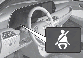
Driver's seat belt warning
As a reminder to the driver, the seat belt warning light will illuminate for approximately 6 seconds each time you place the ignition switch to the ON position regardless of belt fastening. At this time, if the seat belt is not fastened a warning chime will sound for 6 seconds.

Copyright © 2025 www.hpalisadelx.com