Hyundai Palisade: Seat Electrical / Seat Heater (Non-Air Ventilation)
Hyundai Palisade (LX2) 2020-2025 Service Manual / Body Electrical System / Seat Electrical / Seat Heater (Non-Air Ventilation)
Components and components location
| Components |
Driver/Passenger Seat Heater

| 1. Seat cushion heater 2. Seat heater unit (Passenger only) |
3. Seat back heater |
Second Line Seat Heater

| 1. Seat heater unit 2. Seat back heater |
3. Seat cushion heater |
Schematic diagrams
| Components |
Driver/Passenger Seat Heater

Second Line Seat Heater

Repair procedures
| Inspection |
Driver/Passenger
| 1. |
Check for continuity and measure the resistance between terminals.
|

| 2. |
Operate the seat heater after connecting the connector, and then check
the thermostat by measuring the temperature of seat surface.
|
Second Line Seat Heater
| 1. |
Check for continuity and measure the resistance between terminals.
[RH]
[LH]
|


| 2. |
Operate the seat heater after connecting the connector, and then check
the thermostat by measuring the temperature of seat surface.
|
 Seat Heater Switch
Components and components location
Components
1. Front seat heater switch
2. Rear seat heater switch
Schematic diagrams
Circuit Diagram
Front Seat
No
Connector A
1
C_CAN (High)
2
C_CAN (Low)
3
-
4
LIN
5
-
6
Auto hold signal
7
-
8
Battery (+)
9
IGN
10
Illumination (+)
11
-
12
Illumination (-)
13
Ground
14
DETENT
15
-
16
PDW signal
17
Steering wheel heater signal
18
DBC signal
19
ISG signal
20
SVM/RVM signal
21
ISG indicator
22
SVM indicator
23
PDW indicator
24
Steering whell heater indicator
2nd Seat
No
Connector A
1
Battery (+)
2
ISG Power(+)
3
Illumination (+)
4
Sensor REF (+5V)
5
Mode actuator feadback
6
Temperature actuator feedback
7
Mode actuator (Vent)
8
Mode actuator (Defrost)
9
Temperature actuator (Cooling)
10
Temperature actuator (Heating)
11
DETENT (-)
12
K-LINE
13
LIN line (Rear left seat)
14
LIN line (Rear right seat
15
-
16
Illumination (-)
17
IGN 2
18
IGN 1
19
Blower motor (+)
20
-
21
Rear FET (Drain feedback)
22
Rear FET (Gate)
23
Left heater swtich
24
Left heater indicator (High)
25
Left heater indicator (Middle)
26
Left heater indicator (Low)
27
Right heater swtich
28
Right heater indicator (High)
29
Right heater indicator (Middle)
30
Right heater indicator (Low)
31
Sensor ground
32
Ground
Repair procedures
Removal
Front seat
1...
 Seat Heater (Air Ventilation)
Components and components location
Components
Driver/Passenger Seat Heater
1. Seat cushion heater
2. Seat heater unit (Passenger only)
3...
Other information:
Hyundai Palisade (LX2) 2020-2025 Service Manual: Curtain Airbag (CAB) Module
Components and components location Components 1. Curtain Airbag (CAB) Repair procedures Removal 1. Disconnect the battery negative cable and wait for at least 3 minutes before beginning work...
Hyundai Palisade (LX2) 2020-2025 Owner's Manual: Front Seats
WARNING Take the following precautions when adjusting your seat: NEVER attempt to adjust the seat while the vehicle is moving. The seat could respond with unexpected movement and may cause loss of vehicle control resulting in an accident...
Categories
- Manuals Home
- 1st Generation Palisade Owners Manual
- 1st Generation Palisade Service Manual
- Side view mirror adjustment, Folding the side view mirrors
- Theft-alarm system
- Emergency liftgate safety release
- New on site
- Most important about car
How Does the Air Bag System Operate?
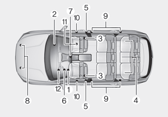
The SRS consists of the following components:
1. Driver's front air bag module
2. Passenger's front air bag module
3. Side air bag modules
4. Curtain air bag modules
5. Retractor pre-tensioner
6. Air bag warning light
7. SRS control module (SRSCM)/
Rollover sensor
8. Front impact sensors
9. Side impact sensors
10.Side pressure sensors
11. Occupant classification system
12. Driver’s knee airbag module

Copyright © 2025 www.hpalisadelx.com