Hyundai Palisade (LX2): Engine Control System / Accelerator Position Sensor (APS)
Description and operation
| Description |
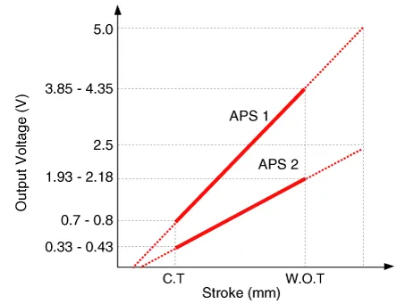
Specifications
| Specification |
|
Accelerator Position |
Output Voltage (V) [Vref = 5V] |
|
|
APS1 |
APS2 |
|
|
C.T |
0.7 - 0.8 |
0.33 - 0.43 |
|
W.O.T |
3.85 - 4.35 |
1.93 - 2.18 |
Schematic diagrams
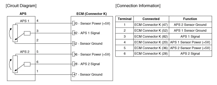
| Circuit Diagram |
Repair procedures
| Inspection |
| 1. |
Connect the diagnostic tool on the Data Link Connector (DLC).
|
| 2. |
Switch "ON" the ignition.
|
| 3. |
Measure the output voltage of the APS 1 and 2 at C.T and W.O.T.
|
|||||||||||
| Removal |
| 1. |
Switch "OFF" the ignition and disconnect the negative (-) battery terminal.
|
| 2. |
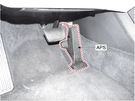
Disconnect the accelerator position sensor connector (A).
|
| 3. |
Remove the accelerator position sensor (B) after loosening the mounting
bolts.
|

| Installation |
| 1. |
Install in the reverse order of removal.
|
Description and operation Description Continuous Variable Valve Timing (CVVT) system advances or retards the valve timing of the intake and exhaust valve in accordance with the ECM control signal which is calculated by the engine speed and load.
Description and operation Description Based on information from various sensors, the ECM can calculate the fuel amount to be injected.
Other information:
Hyundai Palisade (LX2) 2020-2026 Service Manual: A/C Pressure Transducer
Description and operation Description The A/C Pressure Transducer (APT) converts the pressure value of high pressure line into voltage value after measuring it. By converted voltage value, engine ECU controls the cooling fan by operating it high speed or low speed.
Hyundai Palisade (LX2) 2020-2026 Service Manual: Repair procedures
Inspection 1. Turn the ignition switch ON. 2. Manually operate the control switch and measure the voltage of the blower motor. 3. Select the control switch to raise the voltage until it reaches high speed.
Categories
- Manuals Home
- Hyundai Palisade Owners Manual
- Hyundai Palisade Service Manual
- Convenient Features of Your Vehicle
- Power Outlet
- Resetting the Driver's Seat Memory System
- New on site
- Most important about car
