Hyundai Palisade (LX2): Brake System / Brake oil
Specifications
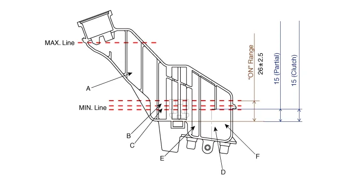
| Specification |
|
Fluid Type |
|
DOT 3 or DOT 4 |
|
Reservoir Quantity (cc) |
||
|
Total |
A + B + C + D + E + F |
460 ± 20 |
|
MAX LEVEL |
A + B + C + D + E |
440 ± 20 |
|
MIN LEVEL |
B + C + D + E |
165 ± 20 |
|
ON LEVEL |
C + D + E |
135 ± 10 |
|
PARTIAL LEVEL |
D |
Pri : 60 ± 5 |
|
D |
Sec : 50 ± 5 |
|
|
CLUTCH LEVEL |
F |
15 ± 5 |
Repair procedures
| Replacement |
|

| 1. |
Turn ignition switch OFF and disconnect the negative (-) battery cable.
|
| 2. |
Disconnect the brake fluid level sensor connector (A).
|

| 3. |
Remove the brake fluid from the master cylinder reservoir with a syringe.
|

| 4. |
Loosen the bleed screw (A) and depress the brake pedal repeatedly several
times until the brake fluid reaches the caliper cylinder.
[Front]
[Rear]
|


| 5. |
Retighten the bleed screw and then make sure the brake fluid in the
reservoir is at the MAX (upper) level line.
|
| 6. |
Loosen the right-rear brake bleed screw (A) to allow air to escape from
the system. Then tighten the bleed screw securely.
[Front]
[Rear]
|


| 7. |
Re-tighten the bleed screw.
|
| 8. |
Have an assistant press the brake pedal several times to pressurize
it and keep it pressed.
|
| 9. |
Pump the brake pedal several times, and then loosen the bleeder screw
until fluid starts to run out without bubbles. Then close the bleeder
screw.
[Front]
[Rear]
|


| 10. |
Repeat the procedure for wheel in the sequence until air bubbles no
longer appear in the fluid.
|
| 11. |
Connect the negative (-) cable.
|
| 12. |
Connect the brake fluid level sensor.
|
Components and components location Components
Components and components location Components 1. Brake member assembly 2. Stop lamp switch 3. Brake pedal arm assembly 4.
Other information:
Hyundai Palisade (LX2) 2020-2026 Service Manual: Auto Defogging Sensor
Description and operation Description The auto defogging sensor is installed on the front window glass. The sensor judges and sends signal if moisture occurs to blow out wind for defogging. The air conditioner control module receives signal from the sensor and restrains moisture and eliminate defog by controlling the intak
Hyundai Palisade (LX2) 2020-2026 Service Manual: Cruise Control (CC) Switch
Components and components location Components 1. Remote control switch (Audio swtich) 2. Remote control switch (Cruise control switch) Schematic diagrams Circuit Diagram Repair procedures Removal 1.
Categories
- Manuals Home
- Hyundai Palisade Owners Manual
- Hyundai Palisade Service Manual
- Power Outlet
- How to reset the power liftgate
- Automatic Transaxle System (A8LF1)
- New on site
- Most important about car
