Hyundai Palisade (LX2): Emission Control System / Components and components location
Hyundai Palisade (LX2) 2020-2026 Service Manual / Emission Control System / Components and components location
| Components Location |
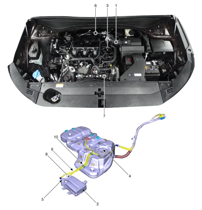
| 1. PCV Valve 2. Canister 3. Purge control solenoid valve (PCSV) 4. Fuel level sensor (FLS) 5. Fuel tank air filter |
6. Catalytic converter (WCC) 7. Catalytic converter (UCC) 8. Vapor hose (Canister ↔ Intake Manifold ) 9. Vapor Hose (Canister ↔ Fuel Tank) 10. Ventilation hose (Canister ↔ Atmosphere) |
|
1. PCV valve |
2. Canister |
|
|
|
|
3. Purge Control Solenoid Valve (PCSV) |
4. Fuel Tank Air Filter |
|
|
|
|
5. Catalytic Converter (WCC, Bank 1) |
5. Catalytic Converter (WCC, Bank 2) |
|
|
|
|
6. Catalytic Converter (UCC) |
|
|
|
|
|
7. Leveling Hose 8. Vapor Hose (Canister ↔ Intake Manifold) 9. Vapor Hose (Canister ↔ Fuel Tank) 10. Ventilation Hose (Canister ↔ Atmosphere) |
|
|
|
|


Schematic Diagram
Other information:
Hyundai Palisade (LX2) 2020-2026 Service Manual: Ambient Temperature Sensor
Description and operation Description The ambient temperature sensor is located at the front of the condenser and detects ambient air temperature. It is a negative type thermistor; resistance will increase with lower temperature, and decrease with higher temperature.
Hyundai Palisade (LX2) 2020-2026 Service Manual: Repair procedures
Variant Coding When you need variant coding: – Replace Front View Camera with a new one ※ EOL Variant Coding and calibration required for new replacement Front View Camera Variant Coding
Categories
- Manuals Home
- Hyundai Palisade Owners Manual
- Hyundai Palisade Service Manual
- Power Outlet
- Electrochromatic Mirror (ECM) with homelink system
- Automatic Transaxle Fluid (ATF)
- New on site
- Most important about car

Copyright © 2026 www.hpalisadelx.com - 0.0121