Hyundai Palisade: Cruise Control System / Description and operation
Hyundai Palisade (LX2) 2020-2025 Service Manual / Engine Electrical System / Cruise Control System / Description and operation
| Cruise Control |
The cruise control system is engaged by the cruise "ON/OFF" main switch located
on the right-hand side of steering wheel column. The system has the capability
to cruise, coast, accelerate and resume speed.
It also has a safety interrupt, engaged upon depressing brake or shifting select
lever.
The ECM is the control module for this system. The main components of cruise
control system are mode control switches, transmission range switch, brake switch,
vehicle speed sensor, ECM and ETS motor that connect throttle body.
The ECM has a low speed limit that prevents system engagement below a minimum
speed of 40km/h (25mph).
The operation of the controller is controlled by mode control switches located
on steering wheel.
Transmission range switch and brake switch are provided to disengage the cruise
control system. The switches are on brake pedal bracket and transmission. When
the brake pedal is depressed or select lever shifted, the cruise control system
is electrically disengaged and the throttle is returned to the idle position.
Cruise main switch (ON/OFF)
The cruise control system is engaged by pressing the cruise "ON/OFF" main switch.
Pressing the cruise "ON/OFF" main switch again releases throttle, clears cruise
memory speed, and puts vehicle in a non-cruise mode.
Set/Coast switch (SET/–)
The "SET/–" switch located on right-hand side of steering wheel column, has
two functions.
The set function - Push the "SET/–" switch and release it at the desired speed.
The SET indicator light in the instrument cluster will illuminate. Release the
accelerator pedal. The desired speed will automatically be maintained.
The coast function - Push the "SET/–" switch and hold it when the cruise control
is on. The vehicle will gradually slow down. Release the switch at the desired
speed. The desired speed will be maintained.
Push the "SET/–" switch and release it quickly. The cruising speed will decrease
by 2.0km/h (1.2mph).
Resume/Accel switch (RES/+)
The "RES/+" switch located on right-hand side of steering wheel column, has
two functions.
The resume function - If any method other than the cruise “ON/OFF” main switch
was used to cancel cruising speed temporarily and the system is still activated,
the most recent set speed will automatically resume when the "RES/+" switch
is pushed. It will not resume, however, if the vehicle speed has dropped below
approximately 40km/h (25mph).
The accel function - Push the "RES/+" switch and hold it when the cruise control
is on. The vehicle will gradually accelerate. Release the switch at the desired
speed. The desired speed will be maintained.
Push the "RES/+" switch and release it quickly. The cruising speed will increase
by 2.0km/h (1.2mph).
Cancel switch (CANCEL)
The cruise control system is temporarily disengaged by pushing the "CANCEL"
switch.
Cruise speed canceled by this switch can be recovered by pushing the "RES/+"
switch.

 Schematic diagrams
System Block Diagram
Component Parts And Function Outline
Component part
Function
Vehicle-speed sensor, ESP/ABS Control Module
Converts vehicle speed to pulse...
Other information:
Hyundai Palisade (LX2) 2020-2025 Service Manual: Front View Camera Unit
Schematic diagrams Circuit Diagram Repair procedures Removal 1. Disconnect the negative (-) battery terminal. 2. Remove the inside rear view mirror cover (A) and rain sensor cover (B)...
Hyundai Palisade (LX2) 2020-2025 Owner's Manual: How to deactivate the Smart Liftgate function using the smart key
1. Door lock 2. Door unlock 3. Liftgate open 4. Panic 5. Remote start If you press any button on the smart key during the Detect and Alert stage, the Smart Liftgate function will be deactivated. Make sure to be aware of how to deactivate the Smart Liftgate function for emergency situations...
Categories
- Manuals Home
- 1st Generation Palisade Owners Manual
- 1st Generation Palisade Service Manual
- Fuse/Relay Panel Description
- Child-Protector Rear Door Locks
- Side view mirror adjustment, Folding the side view mirrors
- New on site
- Most important about car
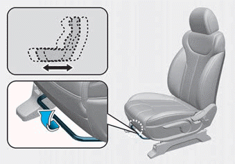
Manual adjustment
The front seat can be adjusted by using the levers located on the outside of the seat cushion. Before driving, adjust the seat to the proper position so that you can easily control the steering wheel, foot pedals and controls on the instrument panel.

Copyright © 2025 www.hpalisadelx.com