Hyundai Palisade (LX2): Floor Console / Floor Console Assembly
Components and components location
| Component Location |
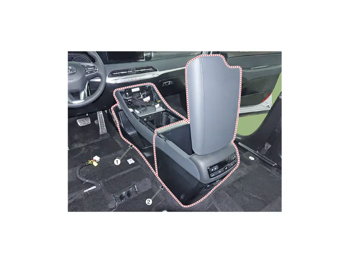
| 1. Front console assembly |
2. Rear console assembly |
Repair procedures
| Replacement |
|

|

| 1. |
Using a flat-tip screwdriver or remover and remove the console upper
cover (A).
|

| 2. |
Press the lock pin and separate the Various connectors (A).
|

| 3. |
Loosen the mounting bolts and remove the rear console assembly (A).
|

| 4. |
Press the lock pin and separate the rear console assembly connector
(A).
|

| 5. |
Using a remover and remove the console side cover (A).
[LH]
[RH]
|


| 6. |
Loosen the mounting screws and remove the front console assembly (A).
|

| 7. |
Press the lock pin and separate the connector (A).
|

| 8. |
To install, reverse removal procedure.
|

Components 1. Floor console rear mounting bracket 2. Rear console assembly 3. Console storage box 4. Front console assembly 5.
Components and components location Component Location 1. Rear console upper cover 2. Rear console under cover Repair procedures Replacement [Upper] • When removing with a flat-tip screwdriver or remover, wrap protective tape around the tools to prevent damage to components.
Other information:
Hyundai Palisade (LX2) 2020-2026 Service Manual: Blower Unit
Components and components location Components Location 1. Blower unit assembly Components 1. Intake seal 2. Intake upper case 3. Intake actuator 4. Intake door 5.
Hyundai Palisade (LX2) 2020-2026 Service Manual: Repair procedures
Inspection Tolerance Compensation Tolerance compensation compensates for the error margins of around view video that occur due to the installation tolerance when the four cameras that comprise the SVM system are installed. You must carry out tolerance compensation if you do any of the following.
Categories
- Manuals Home
- Hyundai Palisade Owners Manual
- Hyundai Palisade Service Manual
- Engine Mechanical System
- Body (Interior and Exterior)
- Lift and Support Points
- New on site
- Most important about car
