Hyundai Palisade: Controller / Heater & A/C Control Unit (Rear)
Hyundai Palisade (LX2) 2020-2025 Service Manual / Heating,Ventilation And Air Conditioning / Controller / Heater & A/C Control Unit (Rear)
Components and components location
| Component |

| Connector Pin Function |
|
Connector |
PIN No |
Pin Function |
Connector |
PIN No |
Pin Function |
|
A |
1 |
Battery |
A |
17 |
IGN2 |
|
2 |
ISG B+ |
18 |
IGN1 |
||
|
3 |
ILL+ (TAIL) |
19 |
Blower Motor (+) |
||
|
4 |
Sensor Ground REF (+5V) |
20 |
- |
||
|
5 |
Mode Control Actuator Feedback |
21 |
Mosfet (DRAIN F/B) |
||
|
6 |
Temperature Actuator Feedback |
22 |
Mosfet (GATE) |
||
|
7 |
Mode Control Actuator (Vent) |
23 |
Heater Switch _ LH |
||
|
8 |
Mode Control Actuator (Defrost) |
24 |
Indicator (HIGH) _ LH |
||
|
9 |
Temperature Control Actuator (Cool) |
25 |
Indicator (MID) _ LH |
||
|
10 |
Temperature Control Actuator (Warm) |
26 |
Indicator (LOW) _ LH |
||
|
11 |
Detent out (-) |
27 |
Heater Switch _ RH |
||
|
12 |
K - Line |
28 |
Indicator (HIGH) _ RH |
||
|
13 |
LIN Left |
29 |
Indicator (MID) _ RH |
||
|
14 |
Lin Right |
30 |
Indicator (LOW) _ RH |
||
|
15 |
- |
31 |
Sensor Ground |
||
|
16 |
ILL - (RHEO) |
32 |
Ground |
Repair procedures
| Replacement |
|

|

| 1. |
Disconnect the negative (-) battery terminal.
|
| 2. |
Using a flat-tip screwdriver or remover and remove the rear console
upper cover (A).
|

| 3. |
Press the lock pin and separate the rear console connector (A) and remove
the rear console upper cover (B).
|

| 4. |
Loosen the mounting screws and remove the rear heater & A/C control
unit (A).
|

| 5. |
To install, reverse removal procedure.
|

 Heater & A/C Control Unit (DATC)
Components and components location
Component
Connector Pin Function
Connector
PIN No
Pin Function
Connector
PIN No
Pin Function
A
1
Battery
A
21
IGN2
2
ISG B+
22
IGN1
3
ILL+ (TAIL)
23
Blower Motor (+)
4
Sensor Ground REF (+5V)
24
Photo Sensor (-)_LEFT
5
Mode Control Actuator Feedback
25
Photo Sensor (-)_RIGHT
6
Temperature Actuator Feedback - Driver
26
Incar Sensor (+)
7
Intake Actuator Feedback
27
Incar Motor (-)
8
Evaporator Temperature Sensor (+)
28
PTC Relay 3
9
Ambient Temperature Sensor (+)
29
PTC Relay 3
10
Mode Control Actuator (Vent)
30
PTC On Signal
11
Mode Control Actuator (Defrost)
31
Detent out (-)
12
Temperature Control Actuator (Cool) - Driver
32
K - Line
13
Temperature Control Actuator (Warm) - Driver
33
P_CAN High
14
Intake Actuator (Fresh Air)
34
P_CAN Low
15
Intake Actuator (Recirculated Air)
35
Mosfet (DRAIN F/B)
16
HTD (Rear Defrost)
36
Mosfet (GATE)
17
Rear Defogging Swich
37
ECV +
18
Clean Signal
38
ECV -
19
Ionizer Diagnosis
39
Sensor Ground
20
ILL - (RHEO)
40
Ground
Connector
PIN No
Pin Function
Connector
PIN No
Pin Function
B
1
Temperature Control Actuator Feedback - Passenger
B
9
-
2
Temperature Control Actuator (Cool) - Passenger
10
-
3
Temperature Control Actuator (Warm) - Passenger
11
-
4
Defogging Actuator Feedback
12
Defogging Sensor TEMP
5
Defogging Actuator (Open)
13
Defogging Sensor SCK
6
Defogging Actuator (Close)
14
Defogging Sensor Data
7
-
15
-
8
Seat Signal PWM - Driver
16
Ground
Repair procedures
Self Diagnosis
1...

Other information:
Hyundai Palisade (LX2) 2020-2025 Owner's Manual: Owner maintenance
WARNING Performing maintenance work on a vehicle can be dangerous. If you lack sufficient knowledge and experience or the proper tools and equipment to do the work, have it done by an authorized HYUNDAI dealer. ALWAYS follow these precautions for performing maintenance work: Park your vehicle on level ground, move the shift button into the P (Park) position, place the ignition switch in the OFF position...
Hyundai Palisade (LX2) 2020-2025 Service Manual: Luggage Room Lamp
Repair procedures Removal 1. Disconnect the negative (-) battery terminal. 2. Remove the luggage room lamp lens with a flat-tip screwdriver. 3. Remove the luggage room lamp bulb...
Categories
- Manuals Home
- 1st Generation Palisade Owners Manual
- 1st Generation Palisade Service Manual
- Theft-alarm system
- Emergency liftgate safety release
- Check Tire Pressure
- New on site
- Most important about car
Locking your vehicle
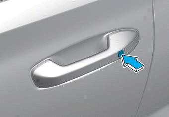
To lock your vehicle using the door handle button or the Smart Key:
1.Make sure all doors, the hood and the liftgate are closed.
2.Make sure you have the smart key in your possession.

Copyright © 2025 www.hpalisadelx.com