Hyundai Palisade: Maintenance / Owner maintenance
WARNING
Performing maintenance work
on a vehicle can be dangerous.
If you lack sufficient knowledge
and experience or the proper
tools and equipment to do the
work, have it done by an authorized
HYUNDAI dealer.
ALWAYS follow these precautions
for performing maintenance
work:
- Park your vehicle on level
ground, move the shift button
into the P (Park) position,
place the ignition switch in
the OFF position.
- Block the tires (front and
back) to prevent the vehicle
from moving.
Remove loose clothing or jewelry
that can become entangled
in moving parts.
- If you must run the engine
during maintenance, do so
out doors or in an area with
plenty of ventilation.
- Keep flames, sparks, or smoking
materials away from the
battery and fuel-related parts.
The following lists are vehicle checks
and inspections that should be performed
by the owner or an authorized
HYUNDAI dealer at the frequencies
indicated to help ensure safe,
dependable operation of your vehicle.
Any adverse conditions should be
brought to the attention of your dealer
as soon as possible.
These Owner Maintenance vehicle
checks are generally not covered by
warranties and you may be charged
for labor, parts and lubricants used.
Owner Maintenance Schedule
When you stop for fuel:
- Check the engine oil level.
- Check the coolant level in the
engine coolant reservoir.
- Check the windshield washer fluid
level.
- Check the tire for low or underinflated
tires.
WARNING
Be careful when checking your
engine coolant level when the
engine is hot. This may result in
coolant being blown out of the
opening and cause serious
burns and other injuries.
While operating your vehicle:
- Note any changes in the sound of
the exhaust or any smell of
exhaust fumes in the vehicle.
- Check for vibrations in the steering
wheel. Notice if there is any
increased steering effort or looseness
in the steering wheel, or
change in its straight-ahead position.
- Notice if your vehicle constantly
turns slightly or "pulls" to one side
when traveling on smooth, level
road.
- When stopping, listen and check
for unusual sounds, pulling to one
side, increased brake pedal travel
or "hard-to-push" brake pedal.
- If any slipping or changes in the
operation of your transmission
occurs, check the transmission
fluid level.
- Check the automatic transmission
P (Park) function.
- Check the parking brake.
- Check for fluid leaks under your
vehicle (water dripping from the air
conditioning system during or after
use is normal).
At least monthly:
- Check coolant level in the engine
coolant reservoir.
- Check the operation of all exterior
lights, including the brake lights,
turn signals and hazard warning
flashers.
- Check the inflation pressures of all
tires including the spare for tires
that are worn, show uneven wear,
or are damaged.
- Check for loose wheel lug nuts.
At least twice a year:
(i.e., every Spring and Autumn)
- Check radiator, heater and air conditioning
hoses for leaks or damage.
- Check windshield washer spray
and wiper operation. Clean wiper
blades with a clean cloth dampened
with washer a fluid.
- Check headlamp alignment.
- Check muffler, exhaust pipes,
shields and clamps.
- Check seat belts for wear and
function.
At least once a year:
- Clean body and door drain holes.
- Lubricate door hinges and hood
hinges.
- Lubricate door and hood locks and
latches.
- Lubricate door rubber weather
strips.
- Lubricate door checker.
- Check the air conditioning system.
- Inspect and lubricate automatic
transmission linkage and controls.
- Clean the battery and terminals.
- Check the brake fluid level.
You should exercise the utmost care
to prevent damage to your vehicle
and injury to yourself whenever performing
any maintenance or inspection
procedures...
Follow Normal Maintenance
Schedule if the vehicle is usually
operated where none of the following
conditions apply. If any of the following
conditions apply, you must follow
the Maintenance Under Severe
Usage Conditions...
Other information:
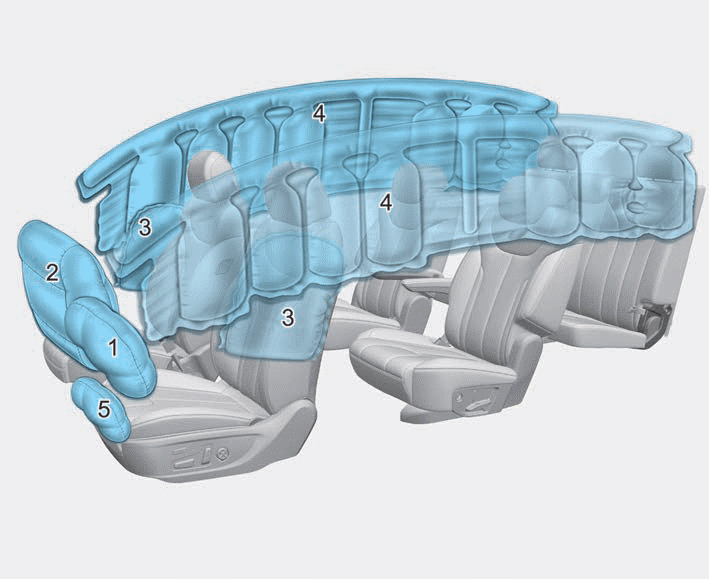
Always fasten your seat belt and
make sure all passengers have fastened
their seat belts before starting
any trip. Air bags are designed to
supplement the seat belt as an additional
safety device, but they are not a
substitute. Most states require all
occupants of a vehicle to wear seat
belts...
Schematic diagrams
ECM Terminal and Input /
Output Signal
ECM Terminal Function
Connector [A]
Pin No
Description
Connected to
1
Ignition Coil (Cylinder #4) control output
Ignition Coil (Cylinder #4)
2
Injector (Cylinder #3) [High] control output
Injector (Cylinder #3)
3
Injector (Cylinder #5) [High] control output
Injector (Cylinder #5)
4
Injector (Cylinder #1) [High] control output
Injector (Cylinder #1)
5
Camshaft Position Sensor (CMPS) [Bank 2 / Exhaust] signal input
Camshaft Position Sensor (CMPS) [Bank 2 / Exhaust]
6
Camshaft Position Sensor (CMPS) [Bank 2 / Intake] signal input
Camshaft Position Sensor (CMPS) [Bank 2 / Intake]
7
Throttle Position Sensor (TPS) 2 signal input
Throttle Position Sensor (TPS) 2
8
-
9
Rail Pressure Sensor (RPS) signal input
Rail Pressure Sensor (RPS)
10
CVVT Oil Temperature Sensor (OTS) signal input
CVVT Oil Temperature Sensor (OTS)
11
-
12
-
13
Sensor power (+5V)
CVVT Oil Temperature Sensor (OTS)
Manifold Absolute Pressure Sensor (MAPS)
14
-
15
-
16
-
17
-
18
-
19
ETC Motor [-] control output
ETC Motor
20
Heated Oxygen Sensor (HO2S) [Bank 1 / Sensor 1] Heater control output
Heated Oxygen Sensor (HO2S) [Bank 1 / Sensor 1]
21
Heated Oxygen Sensor (HO2S) [Bank 2 / Sensor 1] Heater control output
Heated Oxygen Sensor (HO2S) [Bank 2 / Sensor 1]
22
Ignition Coil (Cylinder #5) control output
Ignition Coil (Cylinder #5
23
Injector (Cylinder #6) [High] control output
Injector (Cylinder #6)
24
Injector (Cylinder #2) [High] control output
Injector (Cylinder #2)
25
Injector (Cylinder #4) [High] control output
Injector (Cylinder #4)
26
Camshaft Position Sensor (CMPS) [Bank 1 / Exhaust] signal input
Camshaft Position Sensor (CMPS) [Bank 1 / Exhaust]
27
Camshaft Position Sensor (CMPS) [Bank 1 / Intake] signal input
Camshaft Position Sensor (CMPS) [Bank 1 / Intake]
28
Intake Air Temperature Sensor (IATS) signal input
Intake Air Temperature Sensor (IATS)
29
Manifold Absolute Pressure Sensor (MAPS) signal input
Manifold Absolute Pressure Sensor (MAPS)
30
-
31
-
32
-
33
-
34
Sensor power (+5V)
Camshaft Position Sensor (CMPS) [Bank 1 / Exhaust]
Camshaft Position Sensor (CMPS) [Bank 2 / Intake]
35
-
36
Sensor power (+5V)
Camshaft Position Sensor (CMPS) [Bank 1 / Intake]
Camshaft Position Sensor (CMPS) [Bank 2 / Exhaust]
37
-
38
Purge Control Solenoid Valve (PCSV) control output
Purge Control Solenoid Valve (PCSV)
39
-
40
ETC Motor [+] control output
ETC Motor
41
-
42
-
43
Ignition Coil (Cylinder #1) control output
Ignition Coil (Cylinder #1)
44
Injector (Cylinder #6) [Low] control output
Injector (Cylinder #6)
45
Injector (Cylinder #3) [Low] control output
Injector (Cylinder #3)
46
Injector (Cylinder #2) [Low] control output
Injector (Cylinder #2)
47
Sensor ground
Camshaft Position Sensor (CMPS) [Bank 1 / Exhaust]
Camshaft Position Sensor (CMPS) [Bank 2 / Intake]
48
Sensor ground
Manifold Absolute Pressure Sensor (MAPS)
Oil Pressure Sensor (OPS)
49
Sensor ground
Camshaft Position Sensor (CMPS) [Bank 1 / Intake]
Camshaft Position Sensor (CMPS) [Bank 2 / Exhaust]
50
-
51
-
52
-
53
-
54
Engine Coolant Temperature Sensor (ECTS) signal input
Engine Coolant Temperature Sensor (ECTS)
55
Sensor Shield
Crankshaft Position Sensor (CKPS)
Knock Sensor (KS) #1 [Bank 1]
Knock Sensor (KS) #2 [Bank 2]
56
Sensor power (+5V)
Rail Pressure Sensor (RPS)
57
-
58
Sensor ground
Engine Coolant Temperature Sensor (ECTS)
Rail Pressure Sensor (RPS)
59
Sensor ground
Throttle Position Sensor (TPS) 1
Throttle Position Sensor (TPS) 2
60
Variable Intake Solenoid (VIS) Valve 1 control output
Variable Intake Solenoid (VIS) Valve 1
61
Variable Intake Solenoid (VIS) Valve 2 control output
Variable Intake Solenoid (VIS) Valve 2
62
-
63
-
64
Ignition Coil (Cylinder #2) control output
Ignition Coil (Cylinder #2)
65
Injector (Cylinder #1) [Low] control output
Injector (Cylinder #1)
66
Injector (Cylinder #4) [Low] control output
Injector (Cylinder #4)
67
Injector (Cylinder #5) [Low] control output
Injector (Cylinder #5)
68
Crankshaft Position Sensor (CKPS) [High] signal input
Crankshaft Position Sensor (CKPS)
69
Crankshaft Position Sensor (CKPS) [Low] signal input
Crankshaft Position Sensor (CKPS)
70
-
71
-
72
Oil pressure switch signal input
Oil Pressure Sensor (OPS)
73
-
74
-
75
Throttle Position Sensor (TPS) 1 signal input
Throttle Position Sensor (TPS) 1
76
Knock Sensor (KS) [Bank 1] [Low] signal input
Knock Sensor (KS) [Bank 1]
77
Knock Sensor (KS) [Bank 2] [Low] signal input
Knock Sensor (KS) [Bank 2]
78
Sensor ground
Heated Oxygen Sensor (HO2S) [Bank 2 / Sensor 2]
79
Rc/Rp (Pump Cell Voltage)
Heated Oxygen Sensor (HO2S) [Bank 2 / Sensor 1]
80
VS+ (NERNST Cell Voltage)
Heated Oxygen Sensor (HO2S) [Bank 2 / Sensor 1]
81
Heated Oxygen Sensor (HO2S) [Bank 2 / Sensor 2] signal input
Heated Oxygen Sensor (HO2S) [Bank 2 / Sensor 2]
82
VS+ (NERNST Cell Voltage)
Heated Oxygen Sensor (HO2S) [Bank 1 / Sensor 1]
83
Rc (Compensative Resistance)
Heated Oxygen Sensor (HO2S) [Bank 1 / Sensor 1]
84
Oil Pressure Solenoid Valve control output
Oil Pressure Solenoid Valve
85
Ignition Coil (Cylinder #6) control output
Ignition Coil (Cylinder #6)
86
Ignition Coil (Cylinder #3) control output
Ignition Coil (Cylinder #3)
87
Fuel Pressure Control Valve (FPCV) [High] control output
Fuel Pressure Control Valve (FPCV)
88
Fuel Pressure Control Valve (FPCV) [Low] control output
Fuel Pressure Control Valve (FPCV)
89
Heated Oxygen Sensor (HO2S) [Bank 2 / Sensor 2] Heater control output
Heated Oxygen Sensor (HO2S) [Bank 2 / Sensor 2]
90
Heated Oxygen Sensor (HO2S) [Bank 1 / Sensor 2] Heater control output
Heated Oxygen Sensor (HO2S) [Bank 1 / Sensor 2]
91
CVVT Oil Control Valve (OCV) [Bank 2 / Exhaust] control output
CVVT Oil Control Valve (OCV) [Bank 2 / Exhaust]
92
CVVT Oil Control Valve (OCV) [Bank 1 / Exhaust] control output
CVVT Oil Control Valve (OCV) [Bank 1 / Exhaust]
93
Variable Force Solenoid (VFS) [Bank 2 / Intake] control output
Variable Force Solenoid (VFS) [Bank 2 / Intake]
94
Variable Force Solenoid (VFS) [Bank 1 / Intake] control output
Variable Force Solenoid (VFS) [Bank 1 / Intake]
95
-
96
Sensor power (+5V)
Throttle Position Sensor (TPS) 1
Throttle Position Sensor (TPS) 2
97
Knock Sensor (KS) [Bank 1] [High] signal input
Knock Sensor (KS) [Bank 1]
98
Knock Sensor (KS) [Bank 2] [High] signal input
Knock Sensor (KS) [Bank 2]
99
Sensor ground
Heated Oxygen Sensor (HO2S) [Bank 1 / Sensor 2]
100
-
101
Rc (Compensative Resistance)
Heated Oxygen Sensor (HO2S) [Bank 2 / Sensor 1]
102
VS-/IP- (Common ground)
Heated Oxygen Sensor (HO2S) [Bank 2 / Sensor 1]
103
Heated Oxygen Sensor (HO2S) [Bank 1 / Sensor 2] signal input
Heated Oxygen Sensor (HO2S) [Bank 1 / Sensor 2]
104
VS-/IP- (Common ground)
Heated Oxygen Sensor (HO2S) [Bank 1 / Sensor 1]
105
Rc/Rp (Pump Cell Voltage)
Heated Oxygen Sensor (HO2S) [Bank 1 / Sensor 1]
Connector [K]
Pin No
Description
Connected to
1
ECM ground
Chassis ground
2
ECM ground
Chassis ground
3
Battery power (B+)
Main Relay
4
ECM ground
Chassis ground
5
Battery power (B+)
Main Relay
6
Battery power (B+)
Main Relay
7
-
8
-
9
-
10
-
11
-
12
-
13
Sensor ground
A/C Pressure Transducer (APT)
14
Immobilizer communication line
Immobilizer Control Module
15
Fuel Level Sender (FLS) signal input [Fuel pump]
Fuel Level Sender (FLS)
16
-
17
-
18
-
19
-
20
Sensor power (+5V)
Accelerator Position Sensor (APS) 1
21
Main Relay control output
Main Relay
22
-
23
-
24
-
25
-
26
-
27
-
28
Accelerator Position Sensor (APS) 2 signal input
Accelerator Position Sensor (APS) 2
29
-
30
-
31
-
32
Fuel Level Sender (FLS) signal input [Sub Fuel Sender]
Sub Fuel Level Sender
33
Fuel Pump Relay control output
Fuel Pump Relay
34
-
35
Sensor power (+5V)
A/C Pressure Transducer (APT)
36
Sensor power (+5V)
Accelerator Position Sensor (APS) 2
37
-
38
Vehicle speed signal input
VDC control module
39
-
40
-
41
Start signal input
Start Relay
42
-
43
-
44
-
45
-
46
-
47
Sensor ground
Accelerator Position Sensor (APS) 2
48
-
49
Brake Switch [Test] signal input
Brake Switch
50
-
51
-
52
Sensor ground
Accelerator Position Sensor (APS) 1
53
-
54
-
55
-
56
-
57
-
58
-
59
-
60
P-CAN [Low]
Other control module, Data Link Connector (DLC), Multi-Purpose Check Connector
61
-
62
-
63
-
64
A/C Pressure Transducer (APT) signal input
A/C Pressure Transducer (APT)
65
-
66
-
67
-
68
-
69
LIN (Local Interconnect Network) Serial Bus Line
Battery Sensor
70
-
71
Cooling Fan Relay control output
Cooling Fan Relay
72
Engine speed signal output
Integrated Body Control Unit (IBU)
73
-
74
-
75
-
76
-
77
P-CAN [High]
Other control module, Data Link Connector (DLC), Multi-Purpose Check Connector
78
-
79
Start Relay control output
Start Relay
80
-
81
-
82
Accelerator Position Sensor (APS) 1 signal input
Accelerator Position Sensor (APS) 1
83
Brake Switch [Light] signal input
Brake Switch
84
-
85
-
86
-
87
-
88
-
89
-
90
-
91
-
ECM Terminal Input/ Output signal
Connector [A]
Pin No
Description
Condition
Type
Level
1
Ignition Coil (Cylinder #4) control output
Idle
Pulse
Vpeak = 400V
Frequency : 0 - 58...