Hyundai Palisade: Fuses And Relays / Relay Box (Engine Compartment)
Hyundai Palisade (LX2) 2020-2025 Service Manual / Body Electrical System / Fuses And Relays / Relay Box (Engine Compartment)
Repair procedures
| Inspection |
| 1. |
Disconnect the negative (-) battery terminal.
|
| 2. |
Pull out the relay from the engine compartment relay box.
|
Power Relay (Type A)
|
Check for continuity between the terminals.
| 1. |
There should be continuity between the No.30 and No.87 terminals when
power and ground are connected to the No.85 and No.86 terminals.
|
| 2. |
There should be no continuity between the No.30 and No.87 terminals
when power is disconnected.
[Engine room relay box]
|
Power Relay (Type B)
Check for continuity between the terminals.
A : Wiper relay (Low)
B : Wiper relay (High)
C : Wiper Frt relay
| 1. |
There should be continuity between the No.30 and No.87 terminals when
power and ground are connected to the No.85 and No.86 terminals.
|
| 2. |
There should be continuity between the No.30 and No.87 terminals when
power is disconnected.
|
Power Relay (Type C)
Check for continuity between the terminals.
A : Cooling fan relay
B : Blower Frt relay
C : Rear heated relay
| 1. |
There should be continuity between the No.30 and No.87 terminals when
power and ground are connected to the No.85 and No.86 terminals.
|
| 2. |
There should be no continuity between the No.30 and No.87 terminals
when power is disconnected.
|
Replacement of PCB Block
| 1. |
Disconnect the negative (-) battery terminal.
|
| 2. |
Push 4 hooks in the engine room relay box out to the arrow direction
and put up the PCB block (A).
|
| 3. |
Disconnect the connector and remove the the PCB block (A).
|
Fuse
| 1. |
Be sure there is no play in the fuse holders, and that the fuses are
held securely.
|
| 2. |
Are the fuse capacities for each circuit correct?
|
| 3. |
Are there any blown fuses?
If a fuse is to be replaced, be sure to use a new fuse of the same capacity.
Always determine why the fuse blew first and completely eliminate the
problem before installing a new fuse.
|
Multi Fuse

|
 Relay Box (Passenger Compartment)
Description and operation
Dscription and Operation
ICU (Integrated Central Control Unit)
ICU (Integrated Central Control Unit) is an integrated model of smart junction
block and central gateway...
Other information:
Hyundai Palisade (LX2) 2020-2025 Service Manual: Water pump
Components and components location Components 1. Water pump pulley 2. Water pump 3. Water pump gasket Repair procedures Removal • Be careful not to damage the parts located under the vehicle (floor under cover, fuel filter, fuel tank and canister) when raising the vehicle using the lift...
Hyundai Palisade (LX2) 2020-2025 Service Manual: Repair procedures
On-vehicle Inspection Inspect ignition coil assembly and Perform spark test 1. Check for DTCs. • If a DTC is present, perform troubleshooting in accordance with the procedure for that DTC...
Categories
- Manuals Home
- 1st Generation Palisade Owners Manual
- 1st Generation Palisade Service Manual
- Electronic Child Safety Lock System
- Wireless Cellular Phone Charging System
- Removing and Storing the Spare Tire
- New on site
- Most important about car
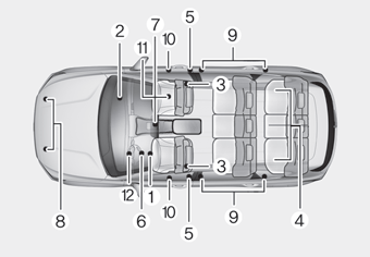
How Does the Air Bag System Operate?

The SRS consists of the following components:
1. Driver's front air bag module
2. Passenger's front air bag module
3. Side air bag modules
4. Curtain air bag modules
5. Retractor pre-tensioner
6. Air bag warning light
7. SRS control module (SRSCM)/
Rollover sensor
8. Front impact sensors
9. Side impact sensors
10.Side pressure sensors
11. Occupant classification system
12. Driver’s knee airbag module
Copyright © 2025 www.hpalisadelx.com


