Hyundai Palisade (LX2): Intake And Exhaust System / Surge Tank
Components and components location
| Components |
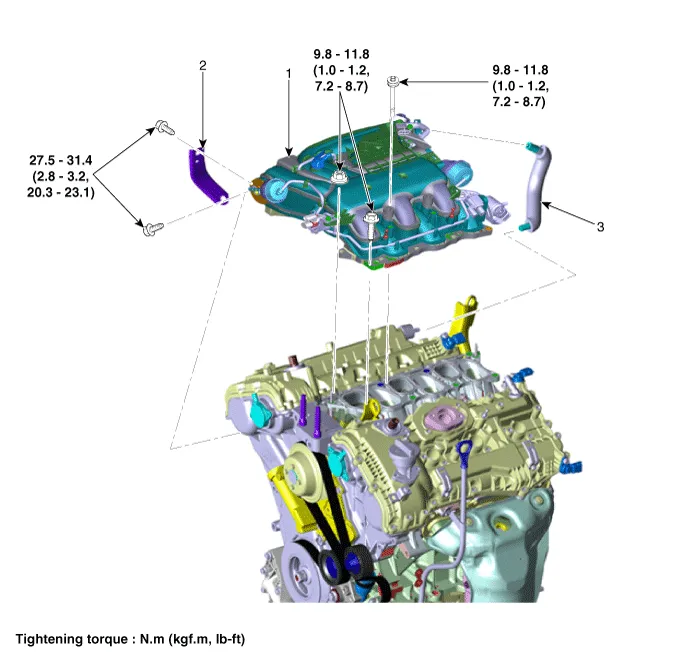
| 1. Surge tank 2. Surge tank stay |
3. Positive crankcase ventilation
(PCV) hose |
Repair procedures
| Removal and Installation |
| 1. |
Remove the engine cover.
(Refer to Engine and Transaxle Assembly - "Engine Cover")
|
| 2. |
Remove the air cleaner assembly.
(Refer to Intake And Exhaust System - "Air Cleaner")
|
| 3. |
Disconnect the wiring connectors and harness clamps and remove the wiring
protector around the surge tank.
|

| 4. |
Disconnect the brake booster vacuum hose (A).
|

| 5. |
Disconnect the purge control solenoid valve (PCSV) hose (A).
|

| 6. |
Disconnect the positive crankcase ventilation (PCV) hose (A).
|

| 7. |
Remove the surge tank stay (A).
|

| 8. |
Remove the surge tank (A).
|

| 9. |
Install in the reverse order of removal.
|
Components and components location Components 1. Air cleaner body 2. Air cleaner cover 3. Air intake hose 4. Air cleaner element 5.
Repair procedures Removal and Installation VIS 1 [Intake Manifold] 1. Disconnect the battery negative terminal. 2.
Other information:
Hyundai Palisade (LX2) 2020-2026 Service Manual: Antenna Coil
Repair procedures Removal 1. Disconnect the negative (-) battery terminal. 2. Remove the crash pad lower panel. (Refer to Body - "Crash Pad Lower Panel") 3.
Hyundai Palisade (LX2) 2020-2026 Service Manual: Description and operation
Description and Operation Blcok Diagram • This system monitors the driving situations through the radar and the camera. Thus, for a situation out of the sensing range, the system may not normally operate.
Categories
- Manuals Home
- Hyundai Palisade Owners Manual
- Hyundai Palisade Service Manual
- Engine Mechanical System
- Resetting the Driver's Seat Memory System
- Body Electrical System
- New on site
- Most important about car
