Hyundai Palisade: Surround View Monitor (SVM) / Troubleshooting

Hyundai Palisade (LX2) 2020-2024 Service Manual / Advanced Driver Assistance System (ADAS) / Surround View Monitor (SVM) / Troubleshooting

Troubleshooting
Hyundai Palisade. Troubleshooting   
1)
After replacing H/UNIT, always check that the system operates properly.
2)
If the failure persists after replacing the H/UNIT, do not replace the unit.
1.
Inspection by DTC Code
Symptom
Probable Cause
Remedy
1. Single DTC code appearance
Loose connector relevant to a certain DTC code
1) Check connection status and reconnect the connector.
Tolerance compensation not completed
1) DTC code appearance (B103000)
2) Perform tolerance compensation.
Disconnected wiring
1) Inspect for conductivity of relevant area of DTC and wiring.
- DTC code generated (B16B700/B16B800/B16B900/B16BA00/B280000/C161600/B162C00)
Faulty wiring connector
1) Check for bent or damaged wiring connector pin.
2) DTC code generated (B16B700/B16B800/B16B900/B16BA00
Faulty H/UNIT connector
1) Check for bent or damaged SVM unit connector pin.
2) DTC code generated (B16B700/B16B800/B16B900/B16BA00)
Faulty H/UNIT single unit or camera
1) Check basic operation and DTC on Diagnostic tool.
2) DTC code generated (B16B700/B16B800/B16B900/B16BA00)
2. Multiple DTC codes appearance
Loose SVM main connector
1) Check connection status and reconnect the connector.
Disconnected wiring
1) Camera power
- In case of 6V or below, inspect relevant wiring.
2) ACC/IGN power
- In case of 7.5V or below, inspect relevant wiring.
3) SVM switch
- In case of 1.75V or higher with the switch ON, inspect relevant wiring.
Faulty wiring connector
1) Check for bent wiring connector pin or interference in neighboring parts.
2) DTC code generated (B16B700/B16B800/B16B900/B16BA00)
Faulty H/UNIT connector
1) Check for bent H/UNIT connector or interference in neighboring parts.
2) DTC code generated (B16B700/B16B800/B16B900/B16BA00)
Faulty H/UNIT single unit
1) If failure recurs after the items above are confirmed normal, replace SVM.

2.
Inspection for Defect in SVM Performance (Image Output)
Symptom
Probable Cause
Remedy
1. No image output :
Black screen, Blue screen, Green screen
Loose H/UNIT or SVM main connector
1) Check connection status and reconnect the connector.
Disconnected H/UNIT or SVM wiring
1) Inspect for conductivity of ACC / IGN / V-OUT / M-CAN terminal wiring
Faulty IPM (SJB)
1) Check power of ACC / IGN terminals : In case of 7.5V or below, inspect IPM (SJB)
Faulty H/UNIT or SVM
1) If failure recurs after the items above are confirmed normal, replace H/UNIT or SVM.
2. Abnormal image output :Noise on screen / lines / cracked display / unable to change display
Loose main connector
1) Check connection status and reconnect the connector.
Disconnected or short-circuited wiring
1) Inspect the wiring relevant to DTC appearance.
Faulty tolerance compensation
1) If the SVM image display is cracked even though the camera display is normal, execute tolerance compensation again.
Faulty camera
1) If both camera display and SVM image display are cracked, inspect the camera.
Faulty IPM (SJB)
1) In case of DTC code (C161600) appearance, inspect IPM (SJB).
Faulty console switch
1) Inspect SVM switch.
- In case of 1.75V or higher with the switch ON, replace the switch.
Faulty H/UNIT or SVM
1) If failure recurs after the items above are confirmed normal, replace H/UNIT or SVM.

3.
Inspection for Faulty PAS Warning Display & Parking Guideline
Symptom
Probable Cause
Remedy
1. Faulty PAS warning display & faulty parking guideline
AVN option information not configured
1) Check and modify AVN option configuration status.
Loose main connector
1) Check connection status and reconnect the connector.
Faulty IPM (SJB)
1) Check that Parking Assist System (PAS) and Steering wheel Angle Sensor (SAS) are normal.
2) Inspect IPM (SJB).
Faulty H/UNIT or SVM
1) If failure recurs after the items above are confirmed normal, replace H/UNIT or SVM.

    Repair procedures

    Inspection Tolerance Compensation Tolerance compensation compensates for the error margins of around view video that occur due to the installation tolerance when the four cameras that comprise the SVM system are installed...

    Surround View Monitor (SVM) Unit

    Components and components location Components No Connector A 1 ACC 2 LED 3 EXT Ground 4 Y Shield 5 - 6 C-CAN Low 7 Y Video ground 8 - 9 - 10 Rear camera power 11 Left camera power 12 Right camera power 13 Ignition 14 AVM switch 15 - 16 C Shield 17 - 18 C- CAN High 19 C video ground 20 C video output 21 - 22 - 23 Left camera ground 24 Right camera ground Repair procedures Removal 1...

    Other information:

    Hyundai Palisade (LX2) 2020-2024 Service Manual: Components and components location


    ..

    Hyundai Palisade (LX2) 2020-2024 Service Manual: Engine Control Module (ECM)


    Schematic diagrams ECM Terminal and Input / Output Signal ECM Terminal Function Connector [A] Pin No Description Connected to 1 Ignition Coil (Cylinder #4) control output Ignition Coil (Cylinder #4) 2 Injector (Cylinder #3) [High] control output Injector (Cylinder #3) 3 Injector (Cylinder #5) [High] control output Injector (Cylinder #5) 4 Injector (Cylinder #1) [High] control output Injector (Cylinder #1) 5 Camshaft Position Sensor (CMPS) [Bank 2 / Exhaust] signal input Camshaft Position Sensor (CMPS) [Bank 2 / Exhaust] 6 Camshaft Position Sensor (CMPS) [Bank 2 / Intake] signal input Camshaft Position Sensor (CMPS) [Bank 2 / Intake] 7 Throttle Position Sensor (TPS) 2 signal input Throttle Position Sensor (TPS) 2 8 -   9 Rail Pressure Sensor (RPS) signal input Rail Pressure Sensor (RPS) 10 CVVT Oil Temperature Sensor (OTS) signal input CVVT Oil Temperature Sensor (OTS) 11 -   12 -   13 Sensor power (+5V) CVVT Oil Temperature Sensor (OTS) Manifold Absolute Pressure Sensor (MAPS) 14 -   15 -   16 -   17 -   18 -   19 ETC Motor [-] control output ETC Motor 20 Heated Oxygen Sensor (HO2S) [Bank 1 / Sensor 1] Heater control output Heated Oxygen Sensor (HO2S) [Bank 1 / Sensor 1] 21 Heated Oxygen Sensor (HO2S) [Bank 2 / Sensor 1] Heater control output Heated Oxygen Sensor (HO2S) [Bank 2 / Sensor 1] 22 Ignition Coil (Cylinder #5) control output Ignition Coil (Cylinder #5 23 Injector (Cylinder #6) [High] control output Injector (Cylinder #6) 24 Injector (Cylinder #2) [High] control output Injector (Cylinder #2) 25 Injector (Cylinder #4) [High] control output Injector (Cylinder #4) 26 Camshaft Position Sensor (CMPS) [Bank 1 / Exhaust] signal input Camshaft Position Sensor (CMPS) [Bank 1 / Exhaust] 27 Camshaft Position Sensor (CMPS) [Bank 1 / Intake] signal input Camshaft Position Sensor (CMPS) [Bank 1 / Intake] 28 Intake Air Temperature Sensor (IATS) signal input Intake Air Temperature Sensor (IATS) 29 Manifold Absolute Pressure Sensor (MAPS) signal input Manifold Absolute Pressure Sensor (MAPS) 30 -   31 -   32 -   33 -   34 Sensor power (+5V) Camshaft Position Sensor (CMPS) [Bank 1 / Exhaust] Camshaft Position Sensor (CMPS) [Bank 2 / Intake] 35 -   36 Sensor power (+5V) Camshaft Position Sensor (CMPS) [Bank 1 / Intake] Camshaft Position Sensor (CMPS) [Bank 2 / Exhaust] 37 -   38 Purge Control Solenoid Valve (PCSV) control output Purge Control Solenoid Valve (PCSV) 39 -   40 ETC Motor [+] control output ETC Motor 41 -   42 -   43 Ignition Coil (Cylinder #1) control output Ignition Coil (Cylinder #1) 44 Injector (Cylinder #6) [Low] control output Injector (Cylinder #6) 45 Injector (Cylinder #3) [Low] control output Injector (Cylinder #3) 46 Injector (Cylinder #2) [Low] control output Injector (Cylinder #2) 47 Sensor ground Camshaft Position Sensor (CMPS) [Bank 1 / Exhaust] Camshaft Position Sensor (CMPS) [Bank 2 / Intake] 48 Sensor ground Manifold Absolute Pressure Sensor (MAPS) Oil Pressure Sensor (OPS) 49 Sensor ground Camshaft Position Sensor (CMPS) [Bank 1 / Intake] Camshaft Position Sensor (CMPS) [Bank 2 / Exhaust] 50 -   51 -   52 -   53 -   54 Engine Coolant Temperature Sensor (ECTS) signal input Engine Coolant Temperature Sensor (ECTS) 55 Sensor Shield Crankshaft Position Sensor (CKPS) Knock Sensor (KS) #1 [Bank 1] Knock Sensor (KS) #2 [Bank 2] 56 Sensor power (+5V) Rail Pressure Sensor (RPS) 57 -   58 Sensor ground Engine Coolant Temperature Sensor (ECTS) Rail Pressure Sensor (RPS) 59 Sensor ground Throttle Position Sensor (TPS) 1 Throttle Position Sensor (TPS) 2 60 Variable Intake Solenoid (VIS) Valve 1 control output Variable Intake Solenoid (VIS) Valve 1 61 Variable Intake Solenoid (VIS) Valve 2 control output Variable Intake Solenoid (VIS) Valve 2 62 -   63 -   64 Ignition Coil (Cylinder #2) control output Ignition Coil (Cylinder #2) 65 Injector (Cylinder #1) [Low] control output Injector (Cylinder #1) 66 Injector (Cylinder #4) [Low] control output Injector (Cylinder #4) 67 Injector (Cylinder #5) [Low] control output Injector (Cylinder #5) 68 Crankshaft Position Sensor (CKPS) [High] signal input Crankshaft Position Sensor (CKPS) 69 Crankshaft Position Sensor (CKPS) [Low] signal input Crankshaft Position Sensor (CKPS) 70 -   71 -   72 Oil pressure switch signal input Oil Pressure Sensor (OPS) 73 -   74 -   75 Throttle Position Sensor (TPS) 1 signal input Throttle Position Sensor (TPS) 1 76 Knock Sensor (KS) [Bank 1] [Low] signal input Knock Sensor (KS) [Bank 1] 77 Knock Sensor (KS) [Bank 2] [Low] signal input Knock Sensor (KS) [Bank 2] 78 Sensor ground Heated Oxygen Sensor (HO2S) [Bank 2 / Sensor 2] 79 Rc/Rp (Pump Cell Voltage) Heated Oxygen Sensor (HO2S) [Bank 2 / Sensor 1] 80 VS+ (NERNST Cell Voltage) Heated Oxygen Sensor (HO2S) [Bank 2 / Sensor 1] 81 Heated Oxygen Sensor (HO2S) [Bank 2 / Sensor 2] signal input Heated Oxygen Sensor (HO2S) [Bank 2 / Sensor 2] 82 VS+ (NERNST Cell Voltage) Heated Oxygen Sensor (HO2S) [Bank 1 / Sensor 1] 83 Rc (Compensative Resistance) Heated Oxygen Sensor (HO2S) [Bank 1 / Sensor 1] 84 Oil Pressure Solenoid Valve control output Oil Pressure Solenoid Valve 85 Ignition Coil (Cylinder #6) control output Ignition Coil (Cylinder #6) 86 Ignition Coil (Cylinder #3) control output Ignition Coil (Cylinder #3) 87 Fuel Pressure Control Valve (FPCV) [High] control output Fuel Pressure Control Valve (FPCV) 88 Fuel Pressure Control Valve (FPCV) [Low] control output Fuel Pressure Control Valve (FPCV) 89 Heated Oxygen Sensor (HO2S) [Bank 2 / Sensor 2] Heater control output Heated Oxygen Sensor (HO2S) [Bank 2 / Sensor 2] 90 Heated Oxygen Sensor (HO2S) [Bank 1 / Sensor 2] Heater control output Heated Oxygen Sensor (HO2S) [Bank 1 / Sensor 2] 91 CVVT Oil Control Valve (OCV) [Bank 2 / Exhaust] control output CVVT Oil Control Valve (OCV) [Bank 2 / Exhaust] 92 CVVT Oil Control Valve (OCV) [Bank 1 / Exhaust] control output CVVT Oil Control Valve (OCV) [Bank 1 / Exhaust] 93 Variable Force Solenoid (VFS) [Bank 2 / Intake] control output Variable Force Solenoid (VFS) [Bank 2 / Intake] 94 Variable Force Solenoid (VFS) [Bank 1 / Intake] control output Variable Force Solenoid (VFS) [Bank 1 / Intake] 95 -   96 Sensor power (+5V) Throttle Position Sensor (TPS) 1 Throttle Position Sensor (TPS) 2 97 Knock Sensor (KS) [Bank 1] [High] signal input Knock Sensor (KS) [Bank 1] 98 Knock Sensor (KS) [Bank 2] [High] signal input Knock Sensor (KS) [Bank 2] 99 Sensor ground Heated Oxygen Sensor (HO2S) [Bank 1 / Sensor 2] 100 -   101 Rc (Compensative Resistance) Heated Oxygen Sensor (HO2S) [Bank 2 / Sensor 1] 102 VS-/IP- (Common ground) Heated Oxygen Sensor (HO2S) [Bank 2 / Sensor 1] 103 Heated Oxygen Sensor (HO2S) [Bank 1 / Sensor 2] signal input Heated Oxygen Sensor (HO2S) [Bank 1 / Sensor 2] 104 VS-/IP- (Common ground) Heated Oxygen Sensor (HO2S) [Bank 1 / Sensor 1] 105 Rc/Rp (Pump Cell Voltage) Heated Oxygen Sensor (HO2S) [Bank 1 / Sensor 1] Connector [K] Pin No Description Connected to 1 ECM ground Chassis ground 2 ECM ground Chassis ground 3 Battery power (B+) Main Relay 4 ECM ground Chassis ground 5 Battery power (B+) Main Relay 6 Battery power (B+) Main Relay 7 -   8 -   9 -   10 -   11 -   12 -   13 Sensor ground A/C Pressure Transducer (APT) 14 Immobilizer communication line Immobilizer Control Module 15 Fuel Level Sender (FLS) signal input [Fuel pump] Fuel Level Sender (FLS) 16 -   17 -   18 -   19 -   20 Sensor power (+5V) Accelerator Position Sensor (APS) 1 21 Main Relay control output Main Relay 22 -   23 -   24 -   25 -   26 -   27 -   28 Accelerator Position Sensor (APS) 2 signal input Accelerator Position Sensor (APS) 2 29 -   30 -   31 -   32 Fuel Level Sender (FLS) signal input [Sub Fuel Sender] Sub Fuel Level Sender 33 Fuel Pump Relay control output Fuel Pump Relay 34 -   35 Sensor power (+5V) A/C Pressure Transducer (APT) 36 Sensor power (+5V) Accelerator Position Sensor (APS) 2 37 -   38 Vehicle speed signal input VDC control module 39 -   40 -   41 Start signal input Start Relay 42 -   43 -   44 -   45 -   46 -   47 Sensor ground Accelerator Position Sensor (APS) 2 48 -   49 Brake Switch [Test] signal input Brake Switch 50 -   51 -   52 Sensor ground Accelerator Position Sensor (APS) 1 53 -   54 -   55 -   56 -   57 -   58 -   59 -   60 P-CAN [Low] Other control module, Data Link Connector (DLC), Multi-Purpose Check Connector 61 -   62 -   63 -   64 A/C Pressure Transducer (APT) signal input A/C Pressure Transducer (APT) 65 -   66 -   67 -   68 -   69 LIN (Local Interconnect Network) Serial Bus Line Battery Sensor 70 -   71 Cooling Fan Relay control output Cooling Fan Relay 72 Engine speed signal output Integrated Body Control Unit (IBU) 73 -   74 -   75 -   76 -   77 P-CAN [High] Other control module, Data Link Connector (DLC), Multi-Purpose Check Connector 78 -   79 Start Relay control output Start Relay 80 -   81 -   82 Accelerator Position Sensor (APS) 1 signal input Accelerator Position Sensor (APS) 1 83 Brake Switch [Light] signal input Brake Switch 84 -   85 -   86 -   87 -   88 -   89 -   90 -   91 -   ECM Terminal Input/ Output signal Connector [A] Pin No  Description Condition Type Level 1 Ignition Coil (Cylinder #4) control output Idle Pulse Vpeak = 400V Frequency : 0 - 58...

    Categories

    Manual adjustment

    The front seat can be adjusted by using the levers located on the outside of the seat cushion. Before driving, adjust the seat to the proper position so that you can easily control the steering wheel, foot pedals and controls on the instrument panel.
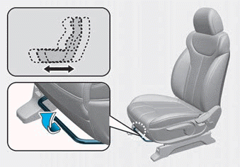
    Hyundai Palisade. Manual adjustment

    read more


    Copyright © 2024 www.hpalisadelx.com