Hyundai Palisade: Cylinder Head Assembly / Valve clearance adjustment
| Valve Clearance Inspection
and Adjustment (MLA) |
| • |
Inspect and adjust the valve clearance with engine cold (engine
coolant temperature : 20°C (68°F)) and cylinder head installed
to the cylinder block.
|
|
| 1. |
Remove the cylinder head cover.
(Refer to Cylinder Head Assembly - "Cylinder Head Cover")
|
| 2. |
Set No.1 cylinder to TDC / compression.
| (1) |
Turn the crankshaft damper pulley clockwise and align its groove
with the timing mark "T" of the lower timing chain cover.

|
| (2) |
Check that the mark of the camshaft timing sprockets are in
straight line on the cylinder head surface as shown in the illustration.
If not, turn the crankshaft clockwise one revolution (360°).
[LH intake]

[LH exhaust]

[RH intake]

[RH exhaust]

|
• |
Do not rotate engine counterclockwise.
|
|
|
|
| 3. |
Inspect the valve clearance.
| (1) |
With No.1 cylinder at TDC, inspect clearances only for the valves
shown below.
[LH]


[RH]


How to Measure :
| a. |
Using a thickness gauge, measure the clearance between
the tappet and the base circle of camshaft.
|
| b. |
Record the out-of-specification valve clearance measurements.
They will be used later to determine the required replacement
adjusting tappet.
|
|
Valve clearance (Engine coolant temperature : 20°C [68°F])
[Specification]
Intake : 0.10 - 0.30 mm (0.0039 - 0.0118 in.)
Exhaust : 0.20 - 0.40 mm (0.0079 - 0.0157 in.)
|
|
| (2) |
Turn the crankshaft pulley clockwise one revolution (360°) and
align the groove with timing mark "T" of the lower timing chain
cover.
|
| (3) |
With the No.4 cylinder at TDC, inspect clearances only for the
valves shown in diagram below.
(Refer to procedure step 1.)
[LH]


[RH]


|
|
| 4. |
Adjust the intake and exhaust valve clearance.
| (1) |
Set the No.1 cylinder to the TDC/compression.
|
| (2) |
Remove the camshaft assembly.
(Refer to Cylinder Head Assembly - "CVVT & Camshaft")
|
| (4) |
Measure the thickness of the removed tappet using a micrometer.

|
| (5) |
Calculate the thickness of a new tappet so that the valve clearance
comes within the specified value.
|
T : Thickness of removed tappet
A : Measured valve clearance
N : Thickness of new tappet
Intake : N = T + [A - 0.20 mm (0.0079 in.)]
Exhaust : N = T + [A - 0.30 mm (0.0118 in.)]
|
|
| (6) |
Select a new tappet with a thickness as close as possible to
the calculated value.
|
• |
Shims are available in 41 size increments of
0.015 mm (0.0006 in.) from 3.00 mm (0.1181 in.)
to 3.60 mm (0.1417 in.).
|
|
|
| (7) |
Place a new tappet on the cylinder head.
|
• |
Apply engine oil around and on top of selected
tappet.
|
|
|
| (8) |
Install the intake and exhaust camshafts.
|
| (9) |
Install the bearing caps.
(Refer to Cylinder Head Assembly - "CVVT & Camshaft")
|
| (10) |
Install the timing chain.
(Refer to Timing System - "Timing Chain")
|
| (11) |
Make two turns on the crankshaft in the operating direction
(clockwise) and realign crankshaft sprocket and camshaft sprocket
timing marks.
[LH intake]

[LH exhaust]

[RH intake]

[RH exhaust]

|
| (12) |
Recheck the valve clearance.
|
Valve clearance (Engine coolant temperature : 20°C [68°F])
[Specification]
Intake : 0.17 - 0.23 mm (0.0067 - 0.0090 in.)
Exhaust : 0.27 - 0.33 mm (0.0106 - 0.0129 in.)
|
|
|
Components and components location
Components
1. LH cylinder head cover
2. LH cylinder head cover gasket
3. LH exhaust CVVT OCV cap
4...
Other information:
Troubleshooting
Symptom
Probable cause
Remedy
Play in steering
Loose yoke plug
Retighten
Loose steering gear mounting bolts
Retighten
Loose or worn tie rod end
Retighten or replace as necessary
Steering wheel operation is not smooth (Insufficient power assist)
V-belt slippage
Readjust
Damaged V-belt
Replace
Low fluid level
Replenish
Air in the fluid
Bleed air
Twisted or damaged hoses
Correct the routing or replace
Insufficient oil pump pressure
Repair or replace the oil pump
Sticky flow control valve
Replace
Excessive internal oil pump leakage
Replace the damaged parts
Excessive oil leaks from rack and pinion in gear box
Replace the damaged parts
Distorted or damaged gear box or valve body seals
Replace
Steering wheel does not return properly
Excessive turning resistance of tie rod end
Replace
Yoke plug excessively tight
Adjust
Tie rod and/or ball joint cannot turn smoothly
Replace
Loose mounting of gear box mounting bracket Worn steering shaft joint and/or
Retighten
Worn steering shaft joint and / or body grommet
Correct or replace
Distorted rack
Replace
Damaged pinion bearing
Replace
Twisted or damaged hoses
Reposition or replace
Damaged oil pressure control valve
Replace
Damaged oil pump input shaft bearing
Replace
Noise
Hissing Noise in Steering Gear
There is some noise with all power steering systems...
WARNING
A vehicle can slip or roll off of a
jack causing serious injury or
death to you or those nearby.
Take the following safety precautions:
Never place any portion of
your body under a vehicle that
is supported by a jack.
NEVER attempt to change a
tire in the lane of traffic...
Categories
Rear seat adjustment
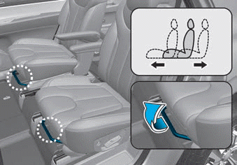
Forward and rearward
(2nd row seat)
To move the seat forward or rearward:
1. Pull the seat slide adjustment
lever up and hold it.
2. Slide the seat to the position you
desire.
read more


 Cylinder Head Cover