Hyundai Palisade: Automatic Transaxle System / Automatic Transaxle Fluid (ATF)
Hyundai Palisade (LX2) 2020-2025 Service Manual / Automatic Transaxle System (A8LF1) / Automatic Transaxle System / Automatic Transaxle Fluid (ATF)
Components and components location
| Components Location |

| 1. ATF Injection plug (Eyebolt) 2. ATF injection plug gasket 3. ATF level check plug |
4. ATF level check plug gasket 5. Drain plug gasket 6. Drain plug |
Repair procedures
| Automatic Transaxle Fluid (ATF) Level Check |

|

| 1. |
Remove the eyebolt (A).
|

| 2. |
Add ATF SP-IV or SP4M-1 700cc to the ATF injection hole (A).
|

| 3. |
Start the engine.
(Don’t step on brake and accelerator simultaneously.)
|
| 4. |
Confirm that the temperature of the automatic transaxle oil temperature
sensor is 50 - 60°C (122 - 140°F) with the diagnostic tool.
|
| 5. |
Shift the select lever slowly from “P” to “D”, then “D” to “P” and repeat
one more at idle.
|

| 6. |
Raise the vehicle, and make sure it is securely supported.
|
| 7. |
Remove the under cover.
(Refer to Engine Mechanical System - "Engine Room Under Cover")
|
| 8. |
Remove the ATF level check plug (A) from the valve body cover.
|


| 9. |
If the ATF flows out of the overflow plug in thin steady stream, the
ATF level is correct.
Then finish the procedure and tighten the ATF level check plug.
|


| 10. |
Install the under cover.
(Refer to Engine Mechanical System - "Engine Room Under Cover")
|
| 11. |
Put down the vehicle with the lift and then tighten the eyebolt.
|


| Replacement |
ATF of 8 speed automatic transaxle doesn’t be replaced. But, if the
vehicle is severe use or business use, replace ATF every 60,000 miles
for severe usage.
Severe usage is defined as
|

| 1. |
Lift the vehicle, and then remove the under cover.
(Refer to Engine Mechanical System - "Engine Room Under Cover")
|
| 2. |
Remove the drain plug (A) and reinstall the drain plug after draining
ATF totally.
|


| 3. |
Put down the vehicle with the lift and then remove the eyebolt (A).
|
| 4. |
Fill the ATF about 5 liters to the injection hole.
|

| 5. |
Check the ATF level.
(Refer to Automatic Transaxle System - "Automatic Transaxle Fluid (ATF)")
|
| 6. |
Then finish check the ATF level procedure and install the under cover.
(Refer to Engine Mechanical System - "Engine Room Under Cover")
|
| 7. |
Put down the vehicle with the lift and then tighten the eyebolt.
|


 Automatic Transaxle
Repair procedures
Removal
•
Carefully install the clamp not to damage the hose...

Other information:
Hyundai Palisade (LX2) 2020-2025 Owner's Manual: TRIP Computer (Cluster type A and type B)
The trip computer is a microcomputer- controlled driver information system that displays information related to driving. Information Some driving information stored in the trip computer (for example Average Vehicle Speed) resets if the battery is disconnected...
Hyundai Palisade (LX2) 2020-2025 Service Manual: Rear Evaporator Core
Repair procedures Replacement 1. Remove the rear heater & A/C unit. (Refer to Rear Heater - "Rear Heater Unit") 2. Loosen the mounting screws, remove the rear heater & A/C unit cover (A) and evaporator core (B)...
Categories
- Manuals Home
- 1st Generation Palisade Owners Manual
- 1st Generation Palisade Service Manual
- Electrochromatic Mirror (ECM) with homelink system
- Auto Hold
- Electronic Child Safety Lock System
- New on site
- Most important about car
How Does the Air Bag System Operate?
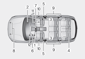
The SRS consists of the following components:
1. Driver's front air bag module
2. Passenger's front air bag module
3. Side air bag modules
4. Curtain air bag modules
5. Retractor pre-tensioner
6. Air bag warning light
7. SRS control module (SRSCM)/
Rollover sensor
8. Front impact sensors
9. Side impact sensors
10.Side pressure sensors
11. Occupant classification system
12. Driver’s knee airbag module

Copyright © 2025 www.hpalisadelx.com