Hyundai Palisade: Engine Control System / Knock Sensor (KS)
Hyundai Palisade (LX2) 2020-2025 Service Manual / Engine Control/Fuel System / Engine Control System / Knock Sensor (KS)
Description and operation
| Description |
Knocking is a phenomenon characterized by undesirable vibration and noise that
can cause engine damage. The two Knock Sensors (KS) are installed inside the
V-valley of the cylinder block and sense engine knocking.
When knocking occurs, the vibration from the cylinder block is applied as pressure
to the piezoelectric element, and the sensor produces voltage signal to ECM.
On receipt of this signal, ECM will control the ignition timing by retarding
the ignition timing and then advancing the ignition timing when the knocking
disappears.
This sequential control can improve engine power, torque and fuel economy.

Specifications
| Specification |
|
Item |
Specification |
|
Capacitance (pF) |
850 - 1,150 |
|
Resistance (MΩ) |
3.90 - 5.84 |
|
pin |
2 |
Schematic diagrams
| Circuit Diagram |

Harness Connector

Repair procedures
| Removal |
| 1. |
Switch "OFF" the ignition and disconnect the negative (-) battery terminal.
|
| 2. |
Disconnect the knock sensor connector (A).
[Knock Sensor (Bank 1)]
[Knock Sensor (Bank 2)]
|
| 3. |
Remove the intake manifold.
(Refer to Engine Mechanical System - "Intake Manifold")
|
| 4. |
Remove the mounting bolt (A), and then remove the sensor from the cylinder
block.
[Knock Sensor (Bank 1)]
[Knock Sensor (Bank 2)]
|
| Installation |
|
| 1. |
Install in the reverse order of removal.
|
 Camshaft Position Sensor (CMPS)
Description and operation
Description
Camshaft Position Sensor (CMPS) is a hall sensor, which detects the camshaft
position by using a hall element...
 Heated Oxygen Sensor (HO2S)
Description and operation
Description
Heated Oxygen Sensor (HO2S), consisting of zirconium and alumina, is installed
on both upstream and downstream of the Manifold Catalytic Converter (MCC) to
detect the air/fuel ratio and send it to the ECM...
Other information:
Hyundai Palisade (LX2) 2020-2025 Service Manual: Hood Lift
Repair procedures Replacement • When removing and installing the hood lifter, an assistant is necessary. • When removing the clips, use a clip remover...
Hyundai Palisade (LX2) 2020-2025 Owner's Manual: Main components of the Occupant Classification System
A detection device located within the front passenger seat cushion. Electronic system to determine whether the passenger air bag systems should be activated or deactivated. An indicator light located on the instrument panel which illuminates the words “OFF” and symbol indicating the front passenger air bag system is deactivated...
Categories
- Manuals Home
- 1st Generation Palisade Owners Manual
- 1st Generation Palisade Service Manual
- Check Tire Pressure
- Rear center seatbelt (3rd row)
- Side view mirror adjustment, Folding the side view mirrors
- New on site
- Most important about car
Manual adjustment
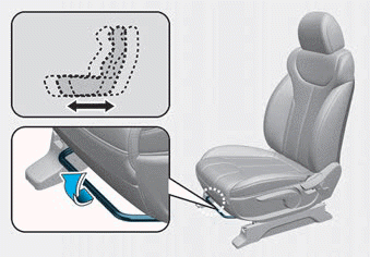
The front seat can be adjusted by using the levers located on the outside of the seat cushion. Before driving, adjust the seat to the proper position so that you can easily control the steering wheel, foot pedals and controls on the instrument panel.

Copyright © 2025 www.hpalisadelx.com


